

 Manufacturers
IEI JUKI-752E

Description
IEI JUKI-750E CPU Board with DX4-100 with LCD/CRT & Ethernet SBC
Part Number
JUKI-752E
Price
Request Quote
Manufacturer
IEI
Lead Time
Request Quote
Category
Single Board Computers
Specifications
Form Factor
Standard AT
Chipset
HM86508
Realtek RTL-8019 chipset
CPU
ACC Maple, includes DX4-100 CPU
Display Memory
1MB on board.
DMA Channels
7
Interrupt Levels
15
Processor
ACC Maple
RAM memory
1MB to 64MB
Real-time clock/calendar
DS12887/BQ3287 or equivalent chip and quartz oscillator, 128B CMOS memory, powered by lithium battery for over 10 years of data retention
Resolution
Support up to 800 x 600 resolution for STN and TFT LCD Flat Panel. And Support 1024x768 256 colors for CRT display.
Shadow RAM memory
System BIOS: 0F0000h ~ 0FFFFFh
Type
10MBps 16-bit Ethernet,Novell NE2000 compatible.
Features
- Dimension: 180mm(W) x 122mm(L), standard AT form factor
- External power connector: 8-pin male connector ( Molex 6410 series compatible)
- Humidity: 5% ~ 95%, non-condense
- Keyboard connector: A 5-pin header on board and 6-pin mini-DIN keyboard connector is located on the mounting bracket.
- Operating Temperature: 0° ~ 55°C
- PC/104 expansion bus: A 64-pin and 40-pin, industrial embedded-PC bus standard.
- Power Consumption: +5V @ 1.65A ( DX4-100MHz,32MB RAM)
- Watch-dog timer: can be set by 1,2,10,20,110,or 220 seconds period. Reset or NMI was generated when CPU did not periodically trigger the timer. Your program use hex 043 and 443 to control the watch-d
Datasheet

Extracted Text
-
DX4-
-
In no event will the manufacturer be liable for direct, indirect, special, incidental, or
JUKI-750E is registered trademarks of ICP Electronics Inc., PC/104 is trademarked of
PC/104 Consortium, IBM PC is a registered trademark of International Business Machines
of American Megatrends, Inc. Other product names mentioned herein are used for
identification purposes only and may be trademarks and/or registered trademarks of their
respective companies.
tered trademark of Intel Corporation. AMI is registered trademarks Corporation. Intel is a regis
Trademarks
ior written permission of the manufacturer.any form without pr
No part of this manual may be reproduced by any mechanical, electronic, or other means in
This document contains proprietary information protected by copyright. All rights are reserved.
vised of the possibility of such damages.en if adev
tial damages arising out of the use or inability to use the product or documentation, consequen
facturer.
d does not represent a commitment on the part of the manureliability, design and function an
The information in this document is subject to change without prior notice in order to improve
Manual first edition Feb.01,1999
All Rights Reserved.
@Copyright 1999
& Ethernet SBC
100 with LCD/CRT
750EJUKI
Contents
2
6
Appendix A. Watch-Dog Timer
1
24...................................Appendix C. I/O Information
22.............................Appendix B. Panel Support List
21..............................
19.................................................4. AMI BIOS Setup
12.........................................................3. Connection
............................................................2. Installation
..........................................................1. Introduction
1
Introduction
Welcome to the JUKI--100 with LCD/CRT & Ethernet Single
Board Computer. The JUKI-750E is an ISA with PC/104 form factor
board, which comes equipped with ACC Maple Chipset (includes DX4-
100 CPU) and advanced high-performance multi-mode I/O,LCD
Controller and Ethernet function, designed for the system
manufacturers, integrators, or VARs that want to provide all the
performance, reliability, and quality at a reasonable price.
An advanced high performance super I/O function are in the Maple
chipset too.. The in chip UARTs are compatible with the NS16C550.
The parallel port and IDE interface are compatible with IBM PC/AT and
The LCD/CRT controller is HMC HM86508 which can provide the LCD
and CRT display at the same time. The LCD interface connector is a
-pin 2.0mm pitch type.
The most outstanding feature in the JUKI-750E is built-in PC/104
expansion bus. Based on the PC/104 bus, you could easily install over
thousands of PC/104 modules from hundreds' vendors in the world.
The JUKI-750E has external power connector that could let it connects
with power supply directly. It is more suitable for your standalone
2
applications.
44
XT architecture's, as well as EPP and ECP.
750E DX4
1.1 Specifications :
--
Computer provides the following specification:
¨
- ·
DMA channels : 7 ·
Interrupt levels : 15 ·
· l-time clock/calendar : DS12887/BQ3287 or equivalent chip and
quartz oscillator, 128B CMOS memory, powered by lithium battery for over
10 years of data retention.
¨
· RAM memory : 1MB to 64MB
Shadow RAM memory : ·
System BIOS : 0F0000h ~ 0FFFFFh
LCD/CRT Interface : ¨
: ·
: Support up to 800 x 600 resolution for STN and TFT LCD Flat
·
Panel. And Support 1024x768 256 colors for CRT display.
Display Memory : ·
Ethernet Interface : ¨
:- ·
: -bit Ethernet,Novell NE2000 compatible. ·
¨
IDE hard disk drive interface : Supports up to two IDE hard disk drives.
·
Floppy disk drive interface : Supports two 2.88 MB, 1.44MB, 1.2MB,
·
720KB, or 360KB floppy disk drives. Can be disabled by BIOS Setup.
3
be disabled by BIOS Setup.Can
Input/Output :
10MBps 16Type
8019 chipsetTL Realtek RChipset
1MB on board.
Resolution
HM86508Chipset
Memory :
Rea
100 CPU : ACC Maple, includes DX4CPU
System :
100 with LCD/CRT & Ethernet Single Board 750E DX4The JUKI
rts : NS16C550 compatible UARTs with
·
-byte FIFOs, data rates are independently programmable
from 115.2K baud down to 50 baud. Modem control circuitry.
Multi-mode Parallel Port : ·
Standard mode - PS/2 compatible bi-directional parallel
port.
- Enhanced parallel port ( EPP) compatible with IEEE 1284
specification.
-
port ( ECP), compatible with IEEE 1248 specification.
: ¨
· -dog timer : can be set by 1,2,10,20,110,or 220 seconds period.
Reset or NMI was generated when CPU did not periodically trigger the timer.
Your program use hex 043 and 443 to control the watch-
system reset.
: A 64-pin and 40-pin, industrial embedded-·
standard.
: 8-pin male
·
compatible)
: A 5--pin mini-·
keyboard connector is located on the mounting bracket.
General : ¨
: +5V @ 1.65A ( DX4- ·
Operating Temperature : 0 ~ 55 · ° °
Humidity : 5% ~ 95%, non- ·
Dimension : 180mm(W) x 122mm(L), standard AT form factor ·
4
condense
C
100MHz,32MB RAM)Power Consumption
DIN pin header on board and 6Keyboard connector
connector ( Molex 6410 series External power connector
PC bus PC/104 expansion bus
dog and generate a
Watch
Industrial features
Microsoft and Hewlett Packard extended capabilities High speed mode
Enhanced mode
C/AT, IBM PC/XT, P
send/receive 16
Two high speed Series po
1.2
In addition to this , the JUKI-
following items:
--·
- ·
·
6-pin Mini-Din to 5- ·
5
pin Din Keyboard/Mouse Adapter Cable
FDD/HDD Cable
232/Printer Cable RS
Computer
Ethernet Single Board 100 with LCD/CRT &750E DX4JUKI
750E package includes the User's Manual
What You Have
2
Installation
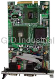
-750E. At first, the layout
of JUKI-
-stem clock
2.1 -750E's Layout
< reference next page >
6
JUKI
also included.
setting, and interrupt IRQ setting for serial ports and parallel port, are
750E's configuration, such as CPU type selection, syJUKI
be careful is described. The jumpers and switches setting for the
750E is shown, and the unpacking information that you should
r describes how to install the JUKIThis chapte
7
8
2.2 -750E
U SPEED SETTING: ·
-02, and the different
table:
1-2 3-4 5-6
OPEN CLOSE
2.3 Watch-Dog Timer
The Watch-
triggered before the time-
again, or activate NMI to CPU. The Watch-Dog Timer is disable by
reading port 843H. The Watch-Dog Timer time-
·-Dog Active Type Setting
DESCRIPTION
2-3 WDT TIME-
1-2 ACTIVATE NMI TO CPU WHEN WDT TIME-
DISABLE WDT
JP4 : WDT TIME-OUT PERIOD ·
1-2 3-4 5-6 7-8
CLOSE
9
220sec
CLOSEOPENOPENCLOSE
OPENOPENOPENCLOSE110sec
CLOSEOPENSECLOOPEN20sec
OPENOPENOPEN10sec
2sec
CLOSECLOSEOPENOPEN
OPENCLOSEOPENOPEN1sec
JP3
OPEN
OUT
OUTRESET WHEN
JP3
JP3 : Watch
1,2,10,20,110 or 220 sec. by JP4.
out period can be set
program operation is abnormal and will issue a reset signal to start
out period ends, otherwise it will assume the
Dog Timer is enabled by reading port 443H. It should be
OPEN100MHz
OPENCLOSECLOSE75MHz
60MHz
CLOSEOPENOPEN
CLOSEOPENCLOSE50MHz
JP2
CPU clock frequency can be selected by JP2 and shown as following
The system clock is generated by the AV9155C
CP
CPU Setting for JUKI
2.4
-
--xMB) is 32-
e
Right now the DOC is available in 2MB to 72MB capacity.
JP5 : DiskOnChip™ ·
1-2 3-4 5-6
CLOSE OPEN OPEN
OPEN CLOSE OPEN
OPEN CLOSE
2.5
via RI pin(Pin 9) of the COM port connector. The max. current is 1A
output to 12V,customer have to make sure to have 12V to supply to
·
RI signal or 5V/12V output selection
Function
RI Signal 2-3 1-2
5V 1-2 2-3
12V 1-2 1-2
10
JP13 JP12
JP12/JP13 : COM2(CN4),Pin 9
the board.
the
with fuse protection for the total two connector’s 5V/12V output. If set
The COM2 (CN4) can supply +5V or +12V power to the serial devices
COM2 RI Pin Setting
OPEN DE000
D6000
CE000
Address
Memory Address Setting
asy and reliable.
Customer don‘t need any extra software utility. It is just “plug and play”,
Because the DOC is 100% compatible to hard disk and DOS.
pin DIP package.2200DOC(MD
Systems. The The DiskOnChip™ Flash Disk Chip(DOC) is produced by M
p™ Flash Disk DiskOnChi
2.6 -232, RS-422 or RS-485 Setting
--422/485 for industrial field
site application..
- ·
JP9 JP10 JP11
Function
RS- 1-2 2-3 1-9 3-
5--
RS- 2-3 1-2 1-2 3-4
5-6 7-8
RS- 1-2 1-2 1-2 3-4
5-6 7-8
2.7 Free IRQ3 and IRQ4 Setting
If customer want to free IRQ3 , IRQ4 for other application. Then have to
disable the COM2 (for IRQ3) or disable the COM1(for IRQ4) by BIOS
the jumper JP16 to free IRQ4.
JP15 JP16
IRQ3 CLOSE
IRQ4 CLOSE
11
Disable COM1
Disable COM2
Release IRQ
setting. And also have to close the jumper JP15 to free IRQ3 and close
485
422
1211 7
10232
COM2
232/422/485 setting JP9/JP10/JP11 : COM2(CN4) RS
232 or RSThe COM2 (CN4) can be set to RS
COM2 RS
3
Connection
-
connectors from the top of the
3.1 Floppy Disk Drive Connector
---chain driver
specified as following table:
CN7 : FDC CONNECTOR ·
1 GROUND 2 REDUCE WRITE
CURRENT#
3 GROUND 4 N/C
5 GROUND 6 N/C
7 GROUND 8
9 GROUND MOTOR ENABLE A#
GROUND DRIVE SELECT B#
GROUND DRIVE SELECT A#
GROUND MOTOR ENABLE B#
GROUND DIRECTION#
GROUND STEP#
GROUND WRITE DATA#
GROUND WRITE GATE#
GROUND TRACK 0#
GROUND WRITE PROTECT#
GROUND READ DATA#
GROUND
GROUND DISK CHANGE#
12
3433
SIDE 1 SELECT#3231
3029
2827
2625
2423
2221
2019
1817
1615
1413
1211
10
INDEX#
DESCRIPTIONPIN NO.DESCRIPTIONPIN NO.
connector cable. The detailed pin assignment of the connector is
pin daisy750E board comes equipped with a 34JUKI
board while it is installed in the chassis.
750E board. You can access most of the indicators to the JUKI
This chapter describes how to connect peripherals, switches and
3.2
drives to the JUKI-
-pin flat-
·
PIN NO. DESCRIPTION PIN NO. DESCRIPTION
1 RESET# 2 GROUND
3 DATA 7 4 DATA 8
5 DATA 6 6 DATA 9
7 DATA 5 8 DATA 10
9 DATA 4 DATA 11
DATA 3 DATA 12
DATA DATA 13
DATA 1 DATA 14
DATA 0 DATA 15
GROUND N/C
N/C GROUND
IOW# GROUND
GROUND
N/C - DEFAULT
N/C GROUND - DEFAULT
INTERRUPT -DEFAULT
N/C
HDC
HDD ACTIVE# GROUND
3.3 Parallel Port
-
--pin flat-
following table:
13
s specified as CN8. The detailed pin assignment of the connector i
cable connector board parallel port, accessed through a 26on
750E includes an This port is usually connected to a printer, The JUKI
4039
HDC CS1#38 CS0#37
SA236SA035
34SA133
IOCS16#3231
3029
BALE 2827
26IOR#25
2423
2221
2019
1817
1615
14 213
1211
10
CN9: IDE Interface Connector
ed as following table:connector is specifi
cable connector. The detailed pin assignment of the with a 40
750E internal controller. The board comes equipped
You can attach two IDE( Integrated Device Electronics) hard disk
IDE Disk Drive Connector
CN8 : Parallel Port Connector ·
DESCRIPTION DESCRIPTION
NO. NO.
1 STROBE# 2 DATA 0
3 DATA 1 4 DATA 2
5 DATA 3 6 DATA 4
7 DATA 5 8 DATA 6
9 DATA 7 ACKNOWLEDGE
PRINTER SELECT AUTO FORM FEED #
ERROR#
PRINTER SELECT LN# GROUND
GROUND GROUND
GROUND GROUND
IOW# GROUND
GROUND
3.4 Serial Ports
-
connect to serial devices or a communication network. One DB-
--
following tables:
·
1 DATA CARRIER DETECT (DCD)
2
3
4 DATA TERMINAL READY (DTR)
5 GROUND
6
7 REQUEST TO SEND (RTS)
8
9
14
RING INDICATOR (RI)
CLEAR TO SEND (CTS)
DATA SET READY (DSR)
(GND)
TRANSMIT DATA (TXD)
RECEIVE DATA (RXD)
DESCRIPTIONPIN NO.
COM1(CN5) : Serial Port Connector
as The detailed pin assignment of the connectors are specified
750E. pin headers are provides by the JUKIconnector and thee 10
9
with Read/Receive 16 byte FIFO serial ports. These ports let you
Ts 750E offers two high speed NS16C550 compatible UARThe JUKI
25
2423
2221
2019
1817
INITIALIZE1615
1413
R EMPTYPAPE12BUSY11
10
PIN PIN
--232 mode ·
PIN NO. DESCRIPTION PIN NO. DESCRIPTION
1 DCD 6 DSR
2 7 RTS
3 TXD 8 CTS
4 DTR 9 RI
5 GND N/C
-pin Header at -422/485 ·
PIN NO. DESCRIPTION PIN NO. DESCRIPTION
1 - 6
2 7 -
3 8
4 9
5
3.5 Keyboard/Mouse Connector
--
-pin Mini-racket for
- ·
PIN NO. DESCRIPTION
1
2 KEYBOARD DATA
3 N/C
4 GROUND
5
- Mouse Connector ·
PIN NO. DESCRIPTION
1 MOUSE DATA
2 N/C
3 GROUND
4
5 MOUSE CLOCK
15
+5V
pin Header CN1 : 5
+5V
KEYBOARD CLOCK
pin Header Keyboard Connector CN16 : 5
single board computer applications.
DIN connector CN16 on the board mounting bis a 6
connector CN16 supports passive backplane applications. Another one
pin header 750E provides two keyboard connectors. A 5The JUKI
10
RXX+ T
RX+ TX
mode RS COM2(CN4) : 2x5
10
RXD
RSpin Header at COM2(CN4) : 2x5
-pin Mini- ·
PIN NO.
1 KEYBOARD DATA
2
3 GROUND
4
5
6
3.6 External Switches and Indicators
ional
install them if you need them. The detailed pin assignment of the
CN3 : RESET BUTTON ·
PIN NO. DESCRIPTION
1 EXTERNAL RESET
2 GROUND
·
-NO DESCRIPTION
1 HDD ACTIVE#
2
3.7
--
--
kplane) application.
CN6 : EXTERNAL POWER CONNECTOR ·
PIN NO. DESCRIPTION
1
2
3 -
4 GROUND
5 GROUND
6 -
7
8
16
+5V
+12V
5V
12V
+12V
+5V
computer( without passive bac
boardcan connect power directly to the CPU board for some single
board external power connector CN6. You 750E has an onThe JUKI
External Power Connector
+5V
PIN
CN10 : IDE LED connector
connectors is specified as following table:
controlling your CPU board. These features are completely opt
There are many external switches and indicators for monitoring and
MOUSE CLOCK
KEYBOARD CLOCK
+5V
MOUSE DATA
CN15 keyboard
DIN Keyboard/Mouse Connector CN2 : 6
3.8 External Speaker
-
·
PIN NO. DESCRIPTION
1
2
3.9 PC/104 Connection Bus
-
of PC/104 modules from hundreds of venders in the world.
NOTE : JUKI-750E allows directly plug in PC/104
module,don‘t need PC/104 Connection Kit.
3.10
--pin connector for the LCD flat panel
-pin Female Connector ·
1 RED 2 GREEN
3 4 NC
5 GROUND 6 GROUND
7 GROUND 8 GROUND
9 NC GROUND
NC NC
NC
17
15
VSYNC14HSYNC13
1211
10
BLUE
CN13 : 15
interface and a DB15 VGA connector.
750E provides a 2x22The JUKI
VGA/LCD Interface Connector
embedded PC bus standard, so you could easily install over thousands
/104 bus is already become the industrial PC/104 modules. The PC
750E’s PC/104 expansion bus let you attach any kind of The JUKI
+5V
SPEAKER SIGNAL
CN18 : SPEAKER
external speaker through the connector CN18 :
e 750E has its own buzzer, you also can connect to thThe JUKI
·
PIN NO. DESCRIPTION PIN NO. DESCRIPTION
1 2
3 GND 4 GND
5 6
7 8 GND
9
GND GND
M
GND
GND N/C
3.11 Lan RJ45 Connector
-750E built-
-
·
1 NC
2 - -
NC
NC NC
·-pin header) for Lan
1 2
3 4
18
+5VLED RX
+5VLED Link
CN17 : LED Connector(4
8. 4.
7.RX+ 3.
RX6.TX
5.TX+
CN15 : Lan RJ45 Connector
2000 compatible) operation.Ethernet(NE
in a RJ45 Lan connector for 10MbpsThe ROCKY
5V44+5V43
4241
ENABLK4039
LP3837
FLM36SHFCLK35
3433
P2332P2231
P2130P2029
P1928P1827
P1726P1625
P1524P1423
P1322P1221
P1120P1019
P918P817
P716P615
P514P413
P312P211
P110P0
FPVEE
+5V+5V
+12V+12V
CN14: LCD Interface Connector
4
-750E use AMI BIOS for system configuration, and the AMI
to provide maximum flexibility in
configuring the system by offering various options which may be
-
4.1 Getting Start
--
Self-
and Initialization and System Configuration Verification. After the
" Hit < Del>, if you want to run SETUP"
4.2
Standard CMOS Setup is the first option on the main menu.
¡E
Date/Time,
¡E
¡E
19
describe more detailed in here.
All of these features are almost the same as common, so we do not
Floppy Disk Type,
Hard Disk Type,
features :
The standard CMOS setup utility is used to configure the following
Standard CMOS Setup
To access AMI BIOS Setup program, press key.
POST routines are completed, the following message appears :
Test routines. These routines will be executed for System Test
Ond on, the BIOS will enter the PowerWhen the system is powere
in the proper usage of these features.
user requirements. This chapter is written to assist you selected for end
BIOS setup program is designed
The JUKI
AMI BIOS Setup
4.3
When you enter the Peripheral Setup, you may see the following items
ing.:
¡E-board IDE : The IDE hard disk drive can be Enable
by this item. When you do not need hard disk, the IDE
¡E-board FDC : The floppy disk drive can be Enable
this item. When you do not need flo
¡ESerial Port 1 : The options are , ,2F8 ,
the I/O address of the serial port ( COMA) or disable it.
¡E
Serial Port 2 : The options are , ,
the I/O address of the serial port 1 ( COMB) or disable it.
¡EParallel Port : The options are , ,
disable it.
¡E
Parallel Port Mode : ROCKY-EPP,ECP,ECP+EPP,
Normal Mode.
20
and
318 provides
the I/O address of the parallel port or
. You can set 278 or 3783BCDisable
. You can set 2F8,or 3F82E8Disable
. You can set 3F8or 3E8Disable
controller can be disabled.
ppy disk, the FDD
by Disable or On
controller can be disabled.
Disable or On
for customer’s sett
Peripheral Setup
AppenWatch-Dog Timer
The Watch-
to crash. This condition may have occurred by external EMI or a
-
The Watch-Dog Timer is controlled by two I/O ports.
Watch-
(hex) Timer.
Disable the Watch-Dog Timer.
(hex)
To enable the Watch-Dog Timer, a read from I/O port 443H must be
performed. This will enable and activate the countdown timer which will
eventually time out and either reset the CPU or cause
does not occur, the Watch-Dog Timer must be periodically refreshed
A tolerance of at least 30% must be maintained to avoid unknown
be very time consuming. Therefore if the time out period has been set
-
21
Timer, otherwise the system will reset.
Dog Note: when exiting a program it is necessary to disable the Watch
7 seconds.to 10 seconds, the I/O port 443H must be read within
routines within the operating system (DOS), such as disk I/O that can
out period that is selected by jumper JP4.
by reading the same I/O port 433H. This must be done within the time
depending on the setting of JP3. To ensure that this reset condition
an NMI
Read843
Dog Enable the refresh theRead443
maskable interrupt (NMI) to bring the system back to a known state.
board will either perform a hardware reset (cold boot) or a non
rking correctly, hardware on the software bug. When the CPU stops wo
can always recover from catastrophic conditions that caused the CPU
Dog Timer is provided to ensure that standalone systems
dix A.
Appendix B. Panel Support List
-750E supports a wide range flat panels. The different flat
panel will need different LCD drive BIOS. The default setting is for
Color DSTN flat panel. The available BIOS for different panels are in
the following list. Please note all the BIOS files already included the
system BIOS and LCD drive BIOS,customer only need to re-
the BIOS flash
– BIOS for MONO DSTN 640x480
For example : HOSIDEN HLM6667
-
-FW-8
11DSTN.ROM – BIOS for Color DSTN 640x480
For example : SANYO LCM--
11TFTS1.ROM – BIOS for TFT 640x480--bit)
11TFTS2.ROM – BIOS for TFT 640x480--bit)
11TFTLP1.ROM – BIOS for TFT 640x480--bit)
11TFTLP2.ROM – BIOS for TFT 640x480--bit)
For example : TOSHIBA LTM09C015A18
11TFT861.ROM – BIOS for TFT 800x600--bit)/
11TFT862.ROM – BIOS for TFT 800x600--bit)
-
-
-
– BIOS for EL 64
-A
–
For example : PANASONIC S817
22
BIOS for PLASMA 640x48011PLASMA.ROM
For example : PLANAR EL640.480
0x48011EL.ROM
02NEC NL8060BC31
04NEC NL8060AC26
05For example : NEC NL8060AC26
SYNC(18/24
SYNC(16
LP(16/24
LP(16
SHARP LQ10D321
TOSHIBA LTM09C015A
For example : HITACHI TX26D60/TX24D55
SYNC (18/24
SYNC (16
RP LM64C35PSHA
22NTK5331
OPTREX DMF_50260NFU
01CASIO MD650TS00
HITACHI LMG5160XUFC
11MLCD.ROM
chip with the file,then power on again.
program
The JUKI
How to update the BIOS by yourself ?
write the file into the Flash.
chip out of socket and then put it back after finish the
programming.
Or,
There also have a utility () and directly re-
program the BIOS under DOS.
For example :
23
C:>FLASH631 11MLCD.ROM
FLASH631.COM2.
Usually the flash type is : ATMEL AT29C010A
d, you should carefully take the FlashTo use this metho
Use EPROM Programmer setting the right Flash type and then 1.
Appendix C. I/O Information
I/O address Range Description
000- DMA Controller #1
020- Interrupt Controller #1, Master
040- 8254 timer
060- 8042 (Keyboard Controller)
070- Real time Clock, NMI (non-maskable
interrupt) Mask
080-
0A0- Interrupt Controller #2
0C0- DMA Controller #2
0F0 Clear Math Coprocessor Busy
0F1 Res
0F2 Core logic programming
configuration
0F8- Math Coprocessor
1F0- Fixed Disk
200- Game I/O
278- Parallel Printer Port 2 (LPT3)
2E8- Serial Port 4
2F8- Serial Port 2
300- Prototype Card
360-
378- Parallel Printer Port 1 (LPT2)
3B0- Monochrome Display and Printer
Adapter (LPT1)
3C0-
3D0- Color/Graphics Monito
3E8- Serial Port 3
3F0- Diskette Controller
3F8- Serial Port 1
443 Watch dog timer enable
843 or 043 Watch dog timer disable
24
3FF
3F7
3EF
r Adapter3DF
Reserved3CF
3BF
37F
Reserved36F
31F
2FF
2EF
27F
207
1F8
0FF
et Math Coprocessor
0DF
0BF
DMA Page Register09F
07F
06F
05F
021
01F
IO Address Map
Memory address Description
0- System memory
A0000- VGA buffer
C0000- VGA BIOS
C8000 – Free for customer application
F0000- System BIOS
1000000- Extend BIOS
IRQ Mapping Chart
System Timer
Controller
FDC Primary IDE
Printer Un
Function
0 Available
1 Available
2 Floppy Disk
3 Available
4 Cascade for DMA controller 1
5 Available
6 Available
7 Available
25
DMA Channel
DMA Channel Assignments
used IRQ15 IRQ7
IRQ14 IRQ6
FPU IRQ13 Unused IRQ5
PS/2 mouse IRQ12 COM1/COM3 IRQ4
Unused IRQ11 COM2/COM4 IRQ3
Unused IRQ10 Cascade to IRQ IRQ2
Unused IRQ9 Keyboard IRQ1
RTC Clock IRQ8 IRQ0
FFFFF
EFFFF
C7FFF
BFFFF
9FFFF0000
1st MB Memory Address Map
Frequently asked questions
Why do business with IEI Boards?

Will there be a warranty for the JUKI-752E?
Which companies are available as carriers?
I don't live in the USA. Will IEI Boards work with me?
Will IEI Boards accept my preferred method of payment?
Why buy from GID?

Quality
We are industry veterans who take pride in our work

Protection
Avoid the dangers of risky trading in the gray market

Access
Our network of suppliers is ready and at your disposal

Savings
Maintain legacy systems to prevent costly downtime

Speed
Time is of the essence, and we are respectful of yours
Related Products
LV Pentium M 1.4 GHz with 1 MB L2 cache

IEI EB-2810/ACE-816A Embedded chassis with ACE-816A 150W ATX power supply
IEI EB-2850GB-8450/ACE-4518AP CPU Board - Embedded chassis for NOVA-8450, with ACE-4518AP-RS,black, ...
IEI ECW-181BS2WD CPU Board - Embedded system with WAFER-GX, AMD Geode GX-466 333MHz CPU, fanless, DC...
Embedded system with WAFER-LUKE, VIA LUKE 1GHz CPU,fanless, DC 12V in, sliver grey, RoHS
IEI ECW-181BS3WD CPU Board - Embedded system with WAFER-LUKE, VIA LUKE 1GHz CPU,fanless, DC 9~36V in...
Request a Quote

The quote request has been received
Close

Facing challenges or have inquiries? Feel free to contact us!
Call Us +1-469-283-2440
What they say about us
FANTASTIC RESOURCE
One of our top priorities is maintaining our business with precision, and we are constantly looking for affiliates that can help us achieve our goal. With the aid of GID Industrial, our obsolete product management has never been more efficient. They have been a great resource to our company, and have quickly become a go-to supplier on our list!
Bucher Emhart Glass
EXCELLENT SERVICE
With our strict fundamentals and high expectations, we were surprised when we came across GID Industrial and their competitive pricing. When we approached them with our issue, they were incredibly confident in being able to provide us with a seamless solution at the best price for us. GID Industrial quickly understood our needs and provided us with excellent service, as well as fully tested product to ensure what we received would be the right fit for our company.
Fuji
HARD TO FIND A BETTER PROVIDER
Our company provides services to aid in the manufacture of technological products, such as semiconductors and flat panel displays, and often searching for distributors of obsolete product we require can waste time and money. Finding GID Industrial proved to be a great asset to our company, with cost effective solutions and superior knowledge on all of their materials, it’d be hard to find a better provider of obsolete or hard to find products.
Applied Materials
CONSISTENTLY DELIVERS QUALITY SOLUTIONS
Over the years, the equipment used in our company becomes discontinued, but they’re still of great use to us and our customers. Once these products are no longer available through the manufacturer, finding a reliable, quick supplier is a necessity, and luckily for us, GID Industrial has provided the most trustworthy, quality solutions to our obsolete component needs.
Nidec Vamco
TERRIFIC RESOURCE
This company has been a terrific help to us (I work for Trican Well Service) in sourcing the Micron Ram Memory we needed for our Siemens computers. Great service! And great pricing! I know when the product is shipping and when it will arrive, all the way through the ordering process.
Trican Well Service
GO TO SOURCE
When I can't find an obsolete part, I first call GID and they'll come up with my parts every time. Great customer service and follow up as well. Scott emails me from time to time to touch base and see if we're having trouble finding something.....which is often with our 25 yr old equipment.
ConAgra Foods