

 Manufacturers
IEI JUKI-760E

Description
AMD-K6 -2/K6 -III/Pentium Processor with LCD/CRT & Ethernet SBC
Part Number
JUKI-760E
Price
Request Quote
Manufacturer
IEI
Lead Time
Request Quote
Category
Single Board Computers
Specifications
System Chipset
Intel ICH
Form Factor
PICMG 1.0
10/100Mbps Ethernet Controller
Realtek RTL8100B IEEE802.3u 100BASE-TX standard
Bus Architecture
32-bit PCI Bus and 16-bit ISA Bus Compatible
Chipset
Ali M1541 supports up to 100MHz system bus and Ali M1543 super I/O controller.
DMA channels
7
Enhanced PCI IDE interface (Ultra DMA/33)
Supports two IDE hard disk drives.
Interrupt levels
15
ISAPLUSTM
Designed to enhance the ISA bus drive capability
L2 Cache Memory
onboard pipelined Burst SRAM 512KB
LCD/CRT Controller
CHIPS 69000 64-bit flat panel controller
On Board I/O
1 Floppy Port (up to 2.88 MB, 3 mode,) 2 Serial Ports (2F8, 3F8,) 1 Parallel Port (ECP, EPP port,) FIR TX/RX Header (3E8)
Operating Humidity
5 ~ 95 % , non-condensing
Operating Temperature
0 ~ 55oC (CPU needs cooler)
Power Consumption
+5V/5A (MMX-233MHz, 32MB EDO RAM) +12V:170mA , -12V:20mA
Processor
Intel Pentium
One Socket 7 supports Intel Pentium® MMX up to 233MHz, AMD K6®-3 up to 500MHz, 100/95/83.3/75/66/60MHz F.S.B.
System Memory
three 168-pin DIMM sockets support 3.3V PC100 SDRAM, up to 768MB, ECC not supported.
USB port
Support two USB ports for future expansion.
Features
- 10/100Mbps Ethernet
- Ali M1541/1543 Chipset
- C&T 69000 HiQPro LCD/CRT Chipset
- DiskOnChip
Datasheet

Extracted Text
–
â â â
-K6-2/K6-Processor
with LCD/CRT & Ethernet SBC
©Copyright 1999 by ICP Electronics Inc. All Rights Reserved. Manual first
edition Jul.01, 1999.
The information in this document is subject to change without prior notice
in order to improve reliability, design and function and does not represent
a commitment on the part of the manufacturer.
In no event will the manufacturer be liable for direct, indirect, special,
incidental, or consequential damages arising out of the use or inability to
use the product or documentation, even if advised of the possibility of
such damages.
This document contains proprietary information protected by copyright. All
rights are reserved. No part of this manual may be reproduced by any
mechanical, electronic, or other means in any form without prior written
permission of the manufacturer.
Trademarks
-760E is a registered trademark of ICP Electronics Inc. IBM PC is a
registered trademark of International Business Machines Corporation.
Intel is a registered trademark of Intel Corporation. AMI is a registered
trademark of American Megatrends, Inc. Other product names mentioned
herein are used for identification purposes only and may be trademarks
and/or registered trademarks of their respective companies.
JUKI
III/PentiumAMD
760E Ver 2.XJUKI
Contents
1. Introduction.......................................................................3
1.1 Specifications..............................................................................4
1.2 What You Have...........................................................................6
2. Installation.........................................................................7
2.1 -.....................................................................8
2.2 ………………………………………………..9
2.3 -...................................................
2.4 Voltage Setting fo................................................
2.5 ..................................................................
2.6 Watch-Dog Timer......................................................................
2.7 DiskOnChip Flash Disk...........................................................
2.8 ..................................................................
2.9 .....................................
2.10 ….........................................
3. Connection......................................................................17
3.1 ......................................................
3.2 -................................................
3.3 Parallel Port...............................................................................
3.4 Serial Ports................................................................................
3.5 .......................................................
3.6 ...............................................
3.7 ..................................................................
3.8 IrDA Infrared Interface Port .......................................................
1
23
23USB Port Connector
22External Switches and Indicators
21Keyboard/Mouse Connector
20
19
18IDE Disk Drive ConnectorPCI E
17Floppy Disk Drive Connector
15RI and COM Port Voltage Selector
14RS232/RS422/RS485 Selector (COMB)
14Clear CMOS Setup..
13
TM
12
12LCD Voltage Setting
12r FLASH ROM
10760ESetting the CPU of JUKI
Unpacking Precautions
760E's LayoutJUKI
3.9 .......................................................................
3.10 ................................................................
3.11 .........................................................................
3.12 ........................................................................
..............................................................28
4.1 Getting Start..............................................................................
4.2 ..............................................................
4.3 .............................................................
4.4 ............................................................
4.5 ........................................................
4.6 ......................................................
4.7 ........................................................................
4.8 Auto Detect Hard Disk ..............................................................
4.9 ……………………………......
4.10 Auto Configuration with Optimal Settings…................................
4.11 Auto Configuration with Fail Save Settings.................................
4.12 ...............................................................
4.13 Exit Without Saving...................................................................
2
5. EKey Function...............................................................42
Appendix A. Watch-Dog Timer...........................................44
Appendix B. ATX Power Supply..........................................45
..............................................46
®
-Processor Voltage..........................48
Appendix E. Flat Panel Connection Module.......................49
2
K6Appendix D. AMD
Appendix C. I/O Information…
41
41Save Settings and Exit
40
40
39Change Supervisor/User Password
38
36eral SetupPeriph
35PCI/PLUG AND PLAY Setup
34Power Management Setup
32Advanced Chipset Setup
30Advanced CMOS Setup
29Standard CMOS Setup
28
4. AMI BIOS Setup
27LCD Connector..
26Fan Connector..
25ector LAN RJ45 Conn
24VGA Connector..
1
Introduction
â â
Welcome to the JUKI-760E 500MHz K6/Pentium with
LCD/CRT & 10/100Mbps Ethernet Single Board Computer. The
-760E is a PICMG bus form factor board. It is equipped with
â â
high performance K6/Pentium up to 500MHz Processor and
advanced high performance multi-mode I/O, designed for the
system manufacturers, integrators, or VARs that want to provide
all the performance, reliability, and quality at a reasonable price.
This board has a built-in DiskOnChip™ (DOC) Flash Disk socket
for embedded application. The DOC Flash Disk provides
are compatibility to hard disk. User can use any DOS
command without any extra software utility. The DOC currently
is available from 2MB to 144MB.
TM
-760E uses C&T 65555 HiQPro LCD/CRT chipset with
2MB EDO RAM display memory. The LCD interface can drive
up to 1280 x 1024 resolution with 256 colors. It supports Mono,
Color STN and TFT flat panel with 3.3V or 5V.
-760E uses the advanced Ali M1541/1543 Chipset which is
100% ISA/PCI compatible chipset with PCI 2.1 standard. In
addition, this board provides three 168-pin sockets for its RAM,
up to 768MB. The DIMM module is 3.3 V SDRAM.
3
JUKI
JUKI
softw
JUKI
1.1 Specifications :
®
: One Socket 7 supports Intel Pentium MMX up to ·
®
-
Architecture: 32-bit PCI Bus and 16-bit ISA Bus Compatible ·
DMA channels : 7 ·
Interrupt levels : 15 ·
: Ali M1541 supports up to 100MHz system bus and Ali ·
M1543 super I/O controller.
L2 Cache Memory: ·
System Memory : three 168-s support 3.3V PC100
·
LCD/CRT Controller :-bit flat panel controller
·
Built-in HiQColor Technology for super clean STN flat panel .
on up to
1280 x 1024, 256 color
1024 x 768, 64K color
800 x 600, 16M color
10/100Mbps Ethernet Controller
·
-TX standard
Dual Auto-sensing interface to 10Mbps or 100Mbps Network
--TX
Full Duplex capability
Full Software driver support
On Board I/O: ·
1 Floppy Port (up to 2.88 MB, 3 mode)
2 Serial Ports (2F8, 3F8)
1 Parallel Port (ECP, EPP port)
USB port : Support two USB ports for future expansion. ·
·
Enhanced PCI IDE interface (Ultra DMA/33) : supports two IDE
·
hard disk drives
4
: designed to enhance the ISA bus drive capabilityISAPLUS
TM
FIR TX/RX Header (3E8)
T and 100BASERJ45 connector for 10BASE
100BASE
: Realtek RTL8139 IEEE802.3u
Display Memory : 2MB EDORAM
CRT Resoluti
TM
CHIPS 65555 64
SDRAM, up to 768MB, ECC not supported.
pin DIMM socket
onboard pipelined Burst SRAM 512KB
Chipset
Bus
.3/75/66MHz F.S.B.3 up to 500MHz, 100/95/83233MHz, AMD K6
Processor
2
E : A special designed 1Kbit EEPROM (non volatile memory)
·
provided to accept read/ write data by customer’s program. It is
useful to store system ID, Password, Critical Data on the board.
-dog timer : can be set by 1, 2, 10, 20, 110 or 220 seconds
·
period. Reset or NMI is generated when CPU does not periodically
trigger the timer. Your program uses hex 043 and 443 to control the
-
Flash Disk - DiskOnChip™ (optional) : The Flash Disk provides ·
software compatibility with hard disk, supports M-Systems. The built-
in True FFS Transparent Flash Block Management and Space
Reclamation will let customer to use the Flash Disk with DOS
command, no need any extra software utility. The DOC currently is
available from 2MB to 144MB.
function. ·
· : +5V/5A (MMX-
+12V:170mA , -:20mA
Operating Humidity : 5 ~ 95 % , non- ·
o
Operating Temperature : 0 ~ 55 ·
5
C (CPU needs cooler)
condensing
12V
233MHz, 32MB EDO RAM) Power Consumption
ATX Power Supply
dog and generate a system reset. watch
Watch
Key
TM
1.2
In addition to this , the JUKI-
the following items:
JUKI- ·
Serial & Parallel Ribbon Cable and Port Bracket ·
·
6-pin Mini--pin Mini--·
pin Mini-
·
If any of these items is missing or damaged, contact the dealer
from whom you purchased the product. Save the shipping
materials and carton in case you want to ship or store the product
in the future.
6
one support disk contains of the needed driver
Din for PS/2 Mouse Adapter Cable.
Din for Keyboard and one 6Din to one 5
FDD/HDD Cable Sets
760E Single Board Computer
E package includes 760User's Manual
What You Have
2
Installation
This chapter describes how to install the JUKI-760E. The layout
of JUKI-760E is shown on the next page and the Unpacking
Precautions that you should be careful with are described on the
for this board’s configuration, such as: CPU type selection,
system clock setting and Watchdog timer.
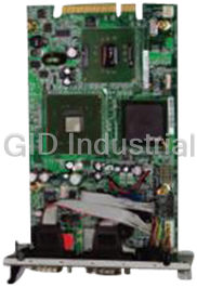
2.1 -760E 's Layout
< please, refer to the next page >
7
JUKI
following page. Also included is the jumpers and switches setting
2.1 -760E 's Layout
8
JUKI
2.2 Unpacking Precautions
Some components on JUKI-760E SBC are very sensitive to static
electric charges and can be damaged by a sudden rush of power.
To protect it from unintended damage, be sure to follow these
ü Ground yourself to remove any static charge before touching your
-760E SBC. You can do it by using a grounded wrist strap at
all times or by frequently touching any conducting materials that is
ü Handle your JUKI-760E SBC by its edges. Don’t touch IC chips,
ü
ü Do not put your JUKI-760E SBC unprotected on a flat surface
Incorrect replacement of battery will cause explosion.
Replace the Lithium battery of the real-time clock only
with the same or eqt dispose of uivalent type part. Don’
the used battery in fire. Dispose of used parts in
accordance with your local regulations.
9
WARNING
because it has components on both sides.
n.Do not plug any connector or jumper while the power is o
leads or circuitry if not necessary.
connected to the ground.
JUKI
precautions:
2.3 Setting the CPU of JUKI-760E
OFF
ON
JP1 : CPU / PCI CLK SETTING ·
PCI CLK
1-2 3-4 5-6 7-8
ON ON ON ON
OFF ON ON ON
OFF OFF ON ON
OFF ON OFF ON
ON OFF OFF ON
OFF OFF OFF ON
·
Voltage 1-6 2-7 3-8 4-9 5-
ON ON ON ON OFF
OFF ON ON ON OFF
ON OFF ON ON OFF
OFF OFF ON ON OFF
ON ON OFF ON OFF
OFF ON OFF ON OFF
ON OFF OFF ON OFF
OFF OFF OFF ON OFF
ON ON ON OFF OFF
OFF ON ON OFF OFF
ON OFF ON OFF OFF
OFF OFF ON OFF OFF
ON ON OFF OFF OFF
OFF ON OFF OFF OFF
ON OFF OFF OFF OFF
OFF OFF OFF OFF OFF
10
2.0
2.1
2.2
2.3
2.4
2.5
2.6
2.7
2.8
2.9
3.0
3.1
3.2
3.3
3.4
3.5
10
JP13 : CPU (V core) Voltage Selector
33MHz100MHz
33MHz95MHz
33MHz83MHz
37MHz75MHz
33MHz66MHz
30MHz60MHz
CPU CLK
JP 1
CPU MULTIPLIER SETTING : ·
Multiplier 1-2 3-4 5-6
2x ON OFF OFF
2.5x ON ON OFF
3.0 x OFF ON OFF
OFF OFF OFF
4.0 x ON OFF ON
4.5 x ON ON ON
5.0 x OFF ON ON
5.5x OFF OFF ON
Win95 will not run stable with all 350MHz and above K6-
system. If you use AMD -2/350MHz to run Win95, oftenly the
‘Windows protection error. You need to restart
your computer’ will appear. This is AMD CPU’s problem. To
debug this problem, you must download and run the program:
amdk6upd.zip from AMD website.
11
message
K6
2
Note:
3.5 x
JP12 :
2.4 Voltage Setting for FLASH ROM
JP18 : Flash ROM Voltage Setting ·
DESCRIPTION
PIN NO.
VOLT. SIZE
1-3 , 2- --
1-3 , 4-6
1MB/2MB 3-5 , 4-6 +5V
1-3 , 4-
2.5 LCD Voltage Setting
· : LCD Voltage Setting
PIN NO. DESCRIPTION
1-2
2-3 +5V
Warning: to
2.6 Watch-Dog Timer
The Watch-
be triggered before the time-out period ends, otherwise it will
assume the program operation is abnormal and will issue a reset
signal to reboot or activate NMI to CPU. The Watch-Dog Timer
.
-Dog Timer Type Setting ·
PIN NO. DESCRIPTION
1-2 NMI
2-3 RESET
OFF Disable WDT
12
JP14 : Watch
is disable by reading port 043H
Dog Timer is enabled by reading port 443H. It should
your LCD display.
wrong voltage setting may cause serious damage
3.3V
& JP22 JP3
MX28F 10001MB+12V6
SST/WINBOND/29EE010
INTEL2MB+12V
T150BXINTEL 28F0011MB+12V4
MANUFACTURER
T Time-out Period ·
1-2 3-4 5-6 7-8
OFF OFF ON OFF
OFF OFF ON ON
OFF ON OFF OFF
OFF ON OFF ON
ON OFF OFF OFF
ON OFF OFF ON
The DOC is software compatible to hard disk. It is just “
”, easy and reliable. Right now, the DOC is available from
·
PIN NO.
1-2
3-4
5-6
7-8 ’
13
Dont Care
DE00H
D600H
CE00H
ADDRESS
JP17 : DOC Memory Address Setting
2MB to 144MB.
play
plug and
2.7 DiskOnChip™ Flash Disk
220 sec.
110 sec.
20 sec.
10 sec.
2 sec.
1 sec.
PERIOD
JP16 : WD
2.8 Clear CMOS Setup
If you forget the CMOS password, you can clear or reset it by
closing the for about 3 seconds then set it back to normal
operation by opening the JP4. Now, the password has been
cleared from your CMOS.
JP4 : Clear CMOS Setup ·
PIN NO. DESCRIPTION
OFF Normal Operation
ON Clear CMOS
the ATX-power connector
from the motherboard in order to
2.9 RS232 / RS422 / RS485 Selector (COM2)
·
PIN NO. DESCRIPTION
1-2
2-3
·
DESCRIPTION PIN NO.
2-3 5-6 8-9 -
1-2 4-5 7-8 -
· : Select the RTS signal to control/enable the RS485
output driver. Please refer to the below table for the
function.
RTS 1 0
RS485 driver
DESCRIPTION
1-2 RTS Select
2-3 -
14
422RS
JP6
inputoutput
JP6
1110RS232
1211RS422/485
JP11 : RS422 / RS232 Selector
RS232
RS422/RS485
JP5 : RS422 / RS485 , RS232 Selector
RS482 or RS485.
Combine the JP5 and JP11 user can select the COM2 as RS232,
clear CMOS.
be able to should be disconnected
Note: If you are using an ATX power supply,
JP4
2.10 RI and COM Port Voltage Selector
The RI pin of COM1 (CN18, pin#9) can be set as RI, +5V or
· JP7 : RI or DC Power Select
PIN NO DESCRIPTION
1-2
2-3 RI
· JP9 : is a DC Power Voltage Selector, combined with JP7
PIN NO DESCRIPTION
1-2 +5V
2-3
15
+12V
DC Power Select (connect to JP9)
+12V mode by setting the JP7 and JP9.
COM1
· JP8 : RI or DC Power Select
PIN NO DESCRIPTION
1-2
2-3 RI
· JP10 : is a DC Power Voltage Selector, combined with JP8
PIN NO DESCRIPTION
1-2 +5V
2-3
16
V input too from power supply.+12
Note : when the output is set as 12V, the board should have
+12V
DC Power Select (connect to JP10)
+12V mode by setting the JP8 and JP10
The RI pin of COM2 (CN17, pin#8) can be set as RI, +5V or
COM2
3
Connection
-
3.1 Floppy Disk Drive Connector
---iver
CN10 : FDD CONNECTOR ·
PIN NO. PIN NO.
1 2
3 4
5 6
7 8
9
WRITE DATA#
WRITE GATE#
WRITE PROTECT#
17
DISK CHANGE#34GROUND33
LECT#SIDE 1 SE32GROUND31
READ DATA#30GROUND29
28GROUND27
TRACK 0#26GROUND25
24GROUND23
22GROUND21
STEP#20GROUND19
DIRECTION#18GROUND17
MOTOR ENABLE B#16GROUND15
DRIVE SELECT A#14GROUND13
DRIVE SELECT B#12GROUND11
MOTOR ENABLE A#10GROUND
INDEX#GROUND
N/CGROUND
N/CGROUND
REDUCE WRITEGROUND
DESCRIPTIONDESCRIPTION
connector cable.
chain drpin daisy760E board is equipped with a 34JUKI
760E board.indicators to the JUKI
This chapter describes how to connect peripherals, switches and
3.2 -
You can attach four IDE (Integrated Device Electronics) hard
disk drives to the JUKI-760E IDE controller.
·
PIN NO. PIN NO.
1 2
3 4
5 6
7 8
9
IOW#
IOR#
GND.
18
GND40HDD ACTIVE#39
HDC CS1#38HDC CS0#37
SA 236SA 035
N/C34SA 133
N/C32INTERRUPT31
DEFAULT30IDE DACK29
GND28IDE CHRDY27
GND2625
GND2423
GND22IDE DRQ21
N/C20GND19
DATA 1518DATA 017
DATA 1416DATA 115
DATA 1314DATA 213
DATA 1212DATA 311
DATA 1110DATA 4
DATA 10DATA 5
DATA 9DATA 6
DATA 8DATA 7
GNDRESET#
DESCRIPTIONDESCRIPTION
ace Connector CN6/CN7 : Primary/Secondary IDE Interf
IDE Disk Drive Connector PCI E
3.3 Parallel Port
This port is usually connected to a printer, The JUKI-
includes an on-board parallel port, accessed through a 26-
flat-
·
PIN NO. PIN NO.
1 2
3 4
5 6
7 8
9 ACKNOWLEDGE
INITIALIZE
19
N/C26GND25
GND24GND23
GND22GND21
GND20GND19
GND18PRINTER SELECT LN#17
16ERROR#15
AUTO FORM FEED #14PRINTER SELECT13
PAPER EMPTY12BUSY11
10DATA 7
DATA 6DATA 5
DATA 4DATA 3
DATA 2DATA 1
DATA 0STROBE#
DESCRIPTIONDESCRIPTION
CN11 : Parallel Port Connector
cable connector CN11.
pin
760E
3.4 Serial Ports
The JUKI-760E offers two high speed NS16C550 compatible
UARTs with Read/Receive 16 byte FIFO serial ports
(COMA/COMB).
-pin D-sub Connector (COM1) ·
PIN NO.
1
2 RECEIVE DATA (RXD)
3 TRANSMIT DATA (TXD)
4
5 GROUND (GND)
6 DATA SET READY (DSR)
7 EST TO SEND (RTS)
8 CLEAR TO SEND (CTS)
9 RING INDICATOR (RI)
CN17 : Serial Port 2x5 pin header Connector (COM2) ·
PIN NO. PIN NO.
1 6
2 D 7
3 8
4 9 RI
5
20
N/C10GND
DTR
CTSTXD
RTSRX
DSRDCD
DESCRIPTIONDESCRIPTION
REQU
DATA TERMINAL READY (DTR)
DATA CARRIER DETECT (DCD)
DESCRIPTION
CN18 : Serial Port 9
3.5 Keyboard/Mouse Connector
-
-pi ·
PIN NO. DESCRIPTION
1
2 KB DATA
3
4
5 +5V
-pin Mini- ·
PIN NO. DESCRIPTION
1 KB DATA
2 MS DATA
3
4 +5V
5
6 MS
CN3 : Ext. PS/2 Mouse 5-pin Header Connector ·
PIN NO. DESCRIPTION
1 MS DATA
2
3
4 +5V
5
21
MS CLOCK
GND
N/C
CLOCK
KB CLOCK
GND
DIN PS/2 Keyboard Connector CN19 : 6
GND
N/C
KB CLOCK
n Header Ext. Keyboard Connector CN2 : 5
mouse and one PS/2 keyboard & mouse connectors.
760E provides one external keyboard ,one external The JUKI
3.6 External Switches and Indicators
There are several external switches and indicators for
monitoring and controlling your CPU board. All the functions are
CN1 : Multi Panel ·
PIN NO. PIN NO.
1. 2
3. 4 N/C
5. 6 GND
7. 8
9. RESET SW GND
11. GND
13. N/C
15. ATX POWER CONTROL
17. ATX POWER BUTTON
19.
22
ATX 5VSB20GND
ATX 5VSB18
16+5V
14IDE LED
12GND
10
KEYLOCK+5V
N/C
N/C
VCCSPEAKER
DESCRIPTIONDESCRIPTION
in the CN1 connector.
3.7 USB Port Connector
--in USB ports for the future ne
· CN8: 2 USB Connectors
PIN NO. PIN NO.
1 5
2 - 6
3 7 -
4 8
--in IrDA port which
(SIR) or Amplitude Shift Keyed IR (ASKIR) interface. If you want
to use the IrDA port, you have to configure the SIR or ASKIR
’model in the BIOS’3.
Connector ·
PIN NO.
1
2
3 IR-
4
5 IR-
6
23
N/C
TX
GND
RX
N/C
VCC
DESCRIPTION
CN13 : IrDA
s Peripheral Setups COM
supports Serial Infrared 760E has a builtJUKI
3.8 IrDA Infrared Interface Port
+5VGND
SBD1SBD0+
SBD1+SBD0
GND+5V
USB1USB0
bus expansion.
w I/O 760E has two builtThe JUKI
The built-in 15-pin VGA connector can be connected directly to
your monochrome CRT monitor as well as high resolution color
CRT monitor.
·-pin Female VGA Connector
PIN NO. DESCRIPTION PIN NO. DESCRIPTION
1 9
2
3
4
5 H-
6 V-
7
8
24
GND
DDC CLK15GND
SYNC14GND
SYNC13GND
DDC DATA12N/C
N/C11BLUE
GND10GREEN
N/CRED
CN15 : 15
3.9 VGA Connector
·
PIN NO. DESCRIPTION PIN NO. DESCRIPTION
1 2
3 4
5 6
7 8
9
3.10 LAN RJ45 Connector
-760E is equipped with a built-in 10/100Mbps Ethernet
Controller. You can connect it to your LAN through RJ45 LAN
·
PIN NO. DESCRIPTION PIN NO. DESCRIPTION
1
2 - -
3.
4.
·
PIN NO. DESCRIPTION
1
2 LAN ACT.
25
VCC
CN12 : LED Connector for LAN
N/C8.N/C
N/C7.RX+
RX6.TX
N/C5.TX+
CN16 : LAN RJ45 Connector
connector. The pin assignments are as following:
JUKI
GROUND10GROUND
GROUNDDDCK*
DDDA*VSYNC
HSYNCBLUE
GREENRED
CN14 : Ext. VGA Connector
3.11 Fan Connector
The JUKI-760E provides one CPU cooling fan connector and
two system fan connectors. These connectors can supply
12V/500mA to the cooling fan. The connector has a “
s rotation signal to the system, so the pin which supplies the fan’
system BIOS knows the fan speed. Please note that only
specified fan offers the rotation signal .
CN4 : CPU Fan Connector ·
·
·
PIN NO. DESCRIPTION
1
2
3
26
GND
+12V
Fan Sensor
CN9 : System2 Fan Connector
CN5 : System1 Fan Connector
rotation”
3.12 LCD Connector
·
PIN NO. PIN NO.
1 2
3 4
5 6
7 8
9
20
M
27
+12V50+12V49
GND48GND47
LP46FPVEE45
FLM44FPVDD43
ENABKL42SHFCLK41
P04039
P138P237
P536P335
P634P433
P832P931
PLCD30PLCD29
P1028P727
P1126P1525
P1224P1323
P1422P1921
P18P1719
P2018P1617
P2216P2315
P2114P2413
P2612P2511
P2710P29
P28P30
P32P35
P31P34
P33VPCLK
DESCRIPTIONDESCRIPTION
U9: LCD Interface Connector
4
etup
The JUKI-760E uses the AMI PCI/ISA BIOS for system
configuration. The AMI BIOS setup program is designed to
provide maximum flexibility in configuring the system by offering
various options which may be selected for end-
requirements. This chapter is written to assist you in the proper
4.1 Getting Start
When you turn on the power button, the BIOS will enter the
--Self-
system test and initialization and system configuration
verification.
" Hit DEL if you want to run SETUP"
The following screen will be displayed at this time.
28
To access AMI PCI/ISA BIOS Setup program, press key.
Test routines. These routines will be executed for OnPower
usage of these features.
user
AMI BIOS S
4.2 Standard CMOS Setup
The standard CMOS Setup is used for basic hardware system
configuration. The main function is for Date/Time setting and
Floppy/Hard Disk setting. Please refer to the following screen for
To set the Date, for example, press either the arrow or key or not.
30
Enabled
nd
nd
CMOS Setup:
setting is pre
customers don
Advanced CMOS Setup
BootUp Num-> to turn on/off the Num-Lock option on a
enhanced keyboard when you boot. If you turn it off, the arrow
keys on the numeric keypad can be used just as the other set of
Floppy Drive Swap > this function enables you to swap the
floppy disk drives via software or without moving the hardware.
Floppy Drive Seek > when this option is turned Enabled, BIOS
will perform a Seek command on floppy drive A: before boot-
Floppy Access Control > to define the read/write access which
is set when booting from a floppy drive.
Hard Disk Access Control > to define the read/write access
.
PS/2 Mouse Support
> to testify whether or not a PS/2 mouse
S.M.A.R.T. for Hard Disks > to allow BIOS to use the System
nagement and R Technologies protocol for reporting
server system information on a network
System Keyboard
> to configure the keyboard. If you set it
Primary Display > to define the type of display monitor of the
system. The Absent option is for network file servers.
Password Check
> to define if a password is necessary or not
Boot to OS/2 > if you run the OS/2 operating system, this option
must be set to yes. It means you permit BIOS to run properly if
OS/2 or any other OS that does not support Plug and Play is
found in your computer.
System BIOS Cacheable
> to define whether or not the
memory segment FOOOH can be read from or written to cache
memory. Setting it Enabled will give faster execution in your
XXXX, 16k Shadow > ROM Shadow is a technique in which
BIOS code is copied from slower ROM to faster RAM. If you
enable it then the BIOS will be executed from the RAM. Each
31
option allows 16KB segment to be shadowed to the RAM.
system.
> to enable or disable the external cache.
nal Cache Exter
for access to the BIOS setup.
Absent, BIOS will not report keyboard errors.
eportingMa
is supported.
which is set when booting from a HDD
up.
arrow keys on the keyboard and vice versa.
Lock
4.4 Advanced Chipset Setup
This setup functions are working mostly for Chipset. These
options are used to change the Chipset‘s registers. Please
carefully change any default setting ,otherwise the system will
SDRAM CAS# Latency >
to specify the CAS latency timing,
ich means when memory receives CAS signal, how many
clock must the memory wait before it starts to read or write data.
SDRAM Burst X-1-1-1-1-1-1-1 >
to enable or disable Burst
DRAM Timing > to specify the timing mode of DRAM. The
Pipe function >
to enable or disable the pipe function.
SDRAM RASJ Precharge Time >
this option specifies the
length of time for Row Address Strobe form SDRAM to
precharge. Options: 2T, 3T, 4T, 5T.
Cycle Time >
to choose the time cycle of
SDRAM RASJ. Options: 7T, 8T, 9T, 10T.
from memory, it has to send RAS signal first and then send CAS
32
signals. Options: 3CLKs, 4CLKs.
ese signal. This option is used to specify the delay between th
when CPU reads/writes data SDRAM RASJ to CAS Delay >
SDRAM RASJ
options are: Normal, Fast, Slow.
mode to write or read the data in SDRAM
wh
run unstably.
Gated Clock > to enable or disable the control of the gated
time and wakeup time of the DRAM sequencer and the DRAM
controller.
Graphic Aperture Size > to define the size of Graphic Aperture.
Options: 4MB, 8MB,….
Primary Frame Buffer > to enable or disable the buffer for
primary frame
VGA Frame Buffer >
video RAM is allowed. will give you better system
performance.
Data Merge > if enabled, only consecutive line
ISA Line Buffer > to enable or disable the buffer for ISA Line.
Delayed Transaction >
delay transaction for PCI specification 2.1.
AT Bus Clock > to specify the I/O bus clock setting.
Memory Hole : to specify the location of a memory hole in the
CMOS RAM. This setting reserve 15MB to 16MB memory
address space for ISA expansion cards that specifically require
this setting. Memory from 15MB and up will be unavailable to
the system because expansion cards can only access memory
33
up to 16MB.
to enable or disable the support for
merged.
ar address can be
Enabled
to specify whether or not a caching of the
, 256MB
4.5 Power Management Setup
Power Management/APM > to enable or disable the Advanced
Green Monitor Power State > to specify the power state of the
monitor after the specified period of display-
Video Power Down Mode >
to specify the power state of the
VESA VGA video subsystem after the specified period of
-
Hard Disk Power Down Mode >
to specify the power state of
the hard disk after the specified period of hard drive-idle has
Standby Time Out >
to specify the length of the system-idle
period while the system is in full power on state. After this period
Suspend Time Out >
to specify the length of the system-idle
period while the system is in Standby state. After this period of
Monitor XXX Port >
Enabling will allow the IRQ input to be
monitored for both inactivating for entering
Auot_mode/SMI_mode and activating for entering Normal_mode.
Power Button Function >
to specify how the power button
RTC Alarm Date > if enabled, the system will wakeup from
ime according to the set time.
34
suspend t
mounted externally on the chassis is used.
time has ended, the system will go into Suspend state.
of time has ended, the system will go into Standby state.
ended.
idle has ended.display
idle has ended.
Power Management feature.
-s PCI function. ‘
All PCI bus slots on the system use INTA#, thus all installed PCI
Plug and Play Aware O/S >
When PNP OS is installed, interrupts will be reassigned by the
OS when the setting is Yes. When a non-PNP OS is installed or
Clear NVRAM on Every Boot > to specify whether BIOS has to
clear NVRAM on every boot or not.
PCI Latency Timer (PCI Clocks) >
to define the latency timing
(PCI clock) for all PCI devices on the PCI bus.
PCI VGA Palette Snoop > this option is useful only for system
with more than one VGA devices connected to it through
different bus (one PCI and one ISA). To enable those various
VGA devices to handle signal from the CPU on each set of
palette registers of every video devices, it must be set .
Offboard PCI IDE Card > to specify if an offboard PCI IDE
is installed in your computer or not. You must specify the slot
Offboard PCI IDE Primary (/Secondary) IRQ >
to specify the
PCI interrupt that is assigned to the Primary (/Secondary) IDE
he offboard PCI IDE controller.
35
channel on t
number on the board which will be used for the card.
card
Enabled
to prevent reassigning of interrupt settings, select setting to No.
Yes or No
slots must be set.
760E boardThe setup help user handles the JUKI
4.6 PCI / PLUG AND PLAY Setup
Allocate IRQ to PCI VGA >
Yes and vice versa.
PCI Slot (1,2,3,4) IRQ Priority > to specify the IRQ priority to
DMA Channel (0,1,3,5,6,7) > to indicate whether or not the
IRQ (3,4,5,7,9,10,11,14,15) > to assign the displayed IRQ to be
used by a legacy ISA adapter card. The settings are ISA/EISA or
PCI/PnP. It is recommended to assign at least 4 IRQ to PCI/PnP.
4.7 Peripheral Setup
This setup is working mostly on Chipset M1543C with super I/O.
The options are used to change the Chipset‘ s registers. Please
carefully change any default setting to meet your application
need perfectly.
Onboard FDC >
to enable the FDC on your board. If you set it
Auto, the BIOS will decide if the FDC should be enabled,
automatically).
Onboard Serial Port 1 (/2) >
to specify the I/O port address of
the serial port 1(/2). If you set it Auto, the BIOS will decide the
correct I/O port address, automatically.
36
DMA channel is assigned for a PnP or ISA card.
be used by the PCI devices on slot 1 to 4.
to allocate IRQ to PCI VGA, answer
Serial Port2 Mode > to specify the mode of serial port 2.
IR Half-Duplex Mode > to specify the mode of IR device that is
Onboard Parallel Port > to specify the I/O port address of the
parallel port.
Parallel Port Mode > to specify the mode of parallel port. The
(normal parallel port mode),
-
(supports devices that comply with the Enhanced Parallel
Port specificati
(supports devices that comply with the Extended
Capabilities Port).
Parallel Port IRQ >
to assign certain IRQ to the parallel port.
Parallel Port DMA Channel >
available only if the parallel port
mode is ECP.
LCD CRT Selection > to specify the display panel type that is
LCD Type >
Please, consult the LCD panel data sheet/specification for the
LCD type (TFT or STN, etc) and the resolution.The followings
are the available list of LCD panels:
x STN
x TFT
x STN
x STN
x TFT
x
x TFT
x TFT
x TFT
x TFT
x 6 STN
x STN
x TFT
x STN
x STN
# x TFT
37
600102416
600#15 1024
1024#14 1280
768#13 1024
600#12 800
00#11 800
600#10 800
600#9 800
600#8 800
768#7 1024
18bit 480#6 640
480#5 640
600#4 800
480#3 640
1024#2 1280
768#1 1024
to choose LCD type that is connected to the system.
connected to the system.
ECP
on),
EPP
(supports bidirectional transfer),DirBi
Normal
options are:
connected to the IR port.
Onboard IDE > to define which on-board IDE controller
channel(s) to be used. Available options are: Primary,
4.8 Auto-Detect Hard Disk
This option detects the parameters of an IDE hard disk drive
(HDD sector, cylinder, head, etc) automatically and will put the
parameters into the Standard CMOS Setup screen. Up to 4 IDE
drives can be detected and the parameters will be listed in the
the next IDE drives.
Note: If your IDE HDD was formatted in previous older system, incorrect
parameters may be detected. In this case, you need to enter the correct
-
38
level format the disk.parameters manually or low
box. Press
Frequently asked questions
Why do business with IEI Boards?

Will there be a warranty for the JUKI-760E?
Which companies are available as carriers?
I don't live in the USA. Will IEI Boards work with me?
Will IEI Boards accept my preferred method of payment?
Why buy from GID?

Quality
We are industry veterans who take pride in our work

Protection
Avoid the dangers of risky trading in the gray market

Access
Our network of suppliers is ready and at your disposal

Savings
Maintain legacy systems to prevent costly downtime

Speed
Time is of the essence, and we are respectful of yours
Related Products
LV Pentium M 1.4 GHz with 1 MB L2 cache

IEI EB-2810/ACE-816A Embedded chassis with ACE-816A 150W ATX power supply

IEI EB-2850GB-8450/ACE-4518AP CPU Board - Embedded chassis for NOVA-8450, with ACE-4518AP-RS,black, ...
IEI ECW-181BS2WD CPU Board - Embedded system with WAFER-GX, AMD Geode GX-466 333MHz CPU, fanless, DC...
Embedded system with WAFER-LUKE, VIA LUKE 1GHz CPU,fanless, DC 12V in, sliver grey, RoHS
IEI ECW-181BS3WD CPU Board - Embedded system with WAFER-LUKE, VIA LUKE 1GHz CPU,fanless, DC 9~36V in...
Request a Quote

The quote request has been received
Close

Facing challenges or have inquiries? Feel free to contact us!
Call Us +1-469-283-2440
What they say about us
FANTASTIC RESOURCE
One of our top priorities is maintaining our business with precision, and we are constantly looking for affiliates that can help us achieve our goal. With the aid of GID Industrial, our obsolete product management has never been more efficient. They have been a great resource to our company, and have quickly become a go-to supplier on our list!
Bucher Emhart Glass
EXCELLENT SERVICE
With our strict fundamentals and high expectations, we were surprised when we came across GID Industrial and their competitive pricing. When we approached them with our issue, they were incredibly confident in being able to provide us with a seamless solution at the best price for us. GID Industrial quickly understood our needs and provided us with excellent service, as well as fully tested product to ensure what we received would be the right fit for our company.
Fuji
HARD TO FIND A BETTER PROVIDER
Our company provides services to aid in the manufacture of technological products, such as semiconductors and flat panel displays, and often searching for distributors of obsolete product we require can waste time and money. Finding GID Industrial proved to be a great asset to our company, with cost effective solutions and superior knowledge on all of their materials, it’d be hard to find a better provider of obsolete or hard to find products.
Applied Materials
CONSISTENTLY DELIVERS QUALITY SOLUTIONS
Over the years, the equipment used in our company becomes discontinued, but they’re still of great use to us and our customers. Once these products are no longer available through the manufacturer, finding a reliable, quick supplier is a necessity, and luckily for us, GID Industrial has provided the most trustworthy, quality solutions to our obsolete component needs.
Nidec Vamco
TERRIFIC RESOURCE
This company has been a terrific help to us (I work for Trican Well Service) in sourcing the Micron Ram Memory we needed for our Siemens computers. Great service! And great pricing! I know when the product is shipping and when it will arrive, all the way through the ordering process.
Trican Well Service
GO TO SOURCE
When I can't find an obsolete part, I first call GID and they'll come up with my parts every time. Great customer service and follow up as well. Scott emails me from time to time to touch base and see if we're having trouble finding something.....which is often with our 25 yr old equipment.
ConAgra Foods