

 Manufacturers
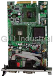
IEI ROCKY-4786EV-R30


Specifications
Form Factor
PICMG
ISAPlus: Design to enhance the ISA bus drive capability(64mA)
Audio
AC’97 CODEC
Board Type
Full Size
Bus
AGP 4X/8X
Chipset
Intel 865G + ICH5
CPU
Socket-478 for Intel Pentium 4 with 533/800MHz FSB
Ethernet
1x 10/100Mbps i82562ET Ethernet; 2x 10/100Mbps i82559 Ethernet (ROCKY-4786E2V)
Operating Humidity
5~95%, non-condensing
Operating Temperature
0 - 60°C (CPU need cooler)
Power Consumption
5~95%, non-condensing, +5V@6.98A (P4 3.3GHz FSB 800MHz; Dual channel DDR400 512mb SDRAM)
SSD
1xCompact Flash Type ?socket
System Memory
Dual channel DDR 333/400 SDRAM socket support up to 2GB
Watchdog Timer
software programmable, support 1~255 second system reset
Features
- 1x 10/100Mbps i82562ET Ethernet, 1x 10/100/1000Mbps i82547 Ethernet by CSA
- 2x 10/100Mbps i82559 Ethernet (ROCKY-4786E2V)
- ATX power control function : meet ACPI 1.1
- Compact Flash Type socket
- Hardware monitoring (CPU Vcore ; CPU/System Fan speed and Thermal)
- Integrated in Intel 865G
- Intel 865G + ICH5
- Socket-478 for Intel Pentium 4 with 533/800MHz FSB
Datasheet

Extracted Text
ROCKY-4786EVG
User Manual
Version 1.2
SOCKET 478 PENTIUM 4 with Ethernet & USB 2.0
March 11, 2004
©Copyright 2004 by ICP Electronic Inc. All Rights Reserved.
1
Copyright Notice
The information in this document is subject to change without prior notice in
order to improve reliability, design and function and does not represent a
commitment on the part of the manufacturer.
In no event will the manufacturer be liable for direct, indirect, special, incidental,
or consequential damages arising out of the use or inability to use the product or
documentation, even if advised of the possibility of such damages.
This document contains proprietary information protected by copyright. All rights
are reserved. No part of this manual may be reproduced by any mechanical,
electronic, or other means in any form without prior written permission of the
manufacturer.
Trademarks
ROCKY-4786EVG is registered trademarks of ICP Electronics Inc.; IBM PC is a
registered trademark of International Business Machines Corporation. INTEL is a
registered trademark of INTEL Corporation. Phoenix-AwardBIOS is registered
trademarks of Phoenix Technologies, LTD, Other product names mentioned herein
are used for identification purposes only and may be trademarks and/or
registered trademarks of their respective companies.
Support
Any questions regarding the content of this manual or related issues can be e-
mailed to us directly at: SUPPORT@IEI.COM.TW
2
Table of Contents
CHAPTER 1 INTRODUCTION .................................................................................4
1.1 SPECIFICATIONS ..................................................................................................................5
1.2 PACKAGE CONTENTS ...........................................................................................................7
CHAPTER 2 INSTALLATION ...................................................................................8
2.1 LAYOUT & DIMENSIONS......................................................................................................9
2.2 UNPACKING PRECAUTIONS ...............................................................................................10
2.3 CLEAR CMOS SETUP........................................................................................................10
2.4 COMPACT FLASH MASTER/SLAVE FUNCTION SETTING ..................................................10
CHAPTER 3 CONNECTION .....................................................................................11
3.1 AUDIO CONNECTOR...........................................................................................................12
3.2 VGA CONNECTOR .............................................................................................................12
3.3 PCI E-IDE DISK DRIVE CONNECTOR ............................................................................13
3.4 PARALLEL PORT CONNECTOR............................................................................................13
3.5 ATX POWER BUTTON CONNECTOR..................................................................................14
3.6 USB PORT CONNECTOR ...................................................................................................14
3.7 SERIAL PORT......................................................................................................................14
3.8 KEYBOARD/MOUSE CONNECTOR......................................................................................15
3.9 IRDA INFRARED INTERFACE PORT...................................................................................15
3.10 FAN CONNECTOR ...........................................................................................................16
3.11 EXTERNAL SWITCHES AND INDICATORS......................................................................16
3.12 LAN CONNECTOR ........................................................................................................17
3.13 SERIAL ATA CONNECTOR.............................................................................................17
3.14 FLOPPY CONNECTOR......................................................................................................18
3.15 COMPACT FLASH STORAGE CARD SOCKET .................................................................19
3.16 DVI (OPTIONAL) .........................................................................................................19
3.17 ATXCTL CONNECTOR ..................................................................................................20
CHAPTER 4 AWARD BIOS SETUP......................................................................21
4.1 INTRODUCTION ..................................................................................................................21
4.2 STARTING SETUP...............................................................................................................21
4.3 USING SETUP.....................................................................................................................21
4.4 MAIN MENU........................................................................................................................23
4.5 STANDARD CMOS SETUP ................................................................................................25
4.6 ADVANCED BIOS FEATURES............................................................................................27
4.7 ADVANCED CHIPSET FEATURES........................................................................................30
4.8 INTEGRATED PERIPHERALS ...............................................................................................32
4.9 POWER MANAGEMENT SETUP ...........................................................................................35
4.10 PNP/PCI CONFIGURATION SETUP...............................................................................37
4.11 PC HEALTH STATUS......................................................................................................38
4.12 FREQUENCY/VOLTAGE CONTROL..................................................................................38
4.13 LOAD FAIL-SAFE DEFAULTS .........................................................................................39
4.14 LOAD OPTIMIZED DEFAULTS ........................................................................................39
4.15 SET PASSWORD .............................................................................................................39
4.16 EXIT SELECTING ............................................................................................................40
APPENDIX A WATCHDOG TIMER ....................................................................41
APPENDIX B ADDRESS MAPPING...................................................................42
APPENDIX C HOW TO UPGRADE A NEW BIOS ........................................44
3
Chapter 1 Introduction
Thank you for choosing ROCKY-4786EVG SOCKET 478 PENTIUM 4 Single Board
Computer. The ROCKY-4786EVG board is an PICMG form factor board, which
comes fully equipped with high performance Processor and advanced high
performance multi-mode I/O, designed for the system manufacturers, integrators,
or VARs that want to provide all the performance, reliability, and quality at a
reasonable price.
In addition, ROCKY-4786EVG built in a 3D AGP 4X controller (Intel 865G), which
provides up to 2048x1536x16-color clear resolution that shares 1/8/16MB system
DDR-SDRAM.
ROCKY-4786EVG supports one or two 64-bit wide DDR400 data channels.
Available bandwidth up to 3.2GB/s in single-channel mode and 6.4GB/s in dual-
channel mode.
The CSA interface connects the GMCH with a Gigabit Ethernet controller.
ROCKY-4786EVG’s built-in ICH5 has 10/100 Fast Ethernet LAN capability. It is
fully integrated 10BASE-T/100BASE-TX LAN solution with high performance
networking functions and low power features.
For applications that needs high speed serial transmission, the ROCKY-4786EVG
provides USB2.0 for your convenience. The high speed USB2.0 host controller
implements an ECHI interface that provides bandwidth up to 480Mb/s.
4
1.1 Specifications
Intel Pentium 4 Processor, supports
CPU(PGA 478)
400/533/800 MHz PSB (SET BY BIOS)
Bus interface PICMG 1.0 compliant, PCI 2.1
Bus speed PCI: 33MHz
DMA channels 7
Interrupt levels 15
Chipset INTEL 865G / ICH5
Two 184-pin DIMM sockets support Dual
Channel DDR333/400 SDRAM .Support one
RAM memory
or two 64-bit wide DDR data channels. The
max. memory supported is up to 2GB.
Up to four PCI Enhanced IDE hard drives.
The Ultra DMA 100 IDE can handle data
Ultra DMA 100 transfer up to 100MB/s. Compatible with
IDE interface existing ATA IDE specifications its best
advantage, so there is no need to do any
changes for users’ current accessories.
Supports up to two floppy disk drives,
Floppy disk drive
5.25”(360KB and 1.2MB) and/or 3.5”
interface
(720KB, 1.44MB, and 2.88MB)
Two RS-232 ports with 16C550 UART (or
compatible) with 16-byte FIFO buffer.
Serial ports Support up to 115.2Kbps. Ports can be
individually configured to COM1, COM2 or
disabled.
Bi-directional Configurable to LPT1, LPT2, LPT3 or
parallel port disabled. Supports EPP/ECP/SPP
Hardware Built-in to monitor power supply voltage
monitor and fan speed status
Supports Serial Infrared(SIR) and
IrDA port
Amplitude Shift Keyed IR(ASKIR) interface
Supports 8 USB 2.0/1.1 ports for future
USB 2.0/1.1 port
expansion
Software Programmable Reset generated
Watchdog timer when CPU does not periodically trigger the
timer.
5
Supports Two independent serial ATA
Serial ATA channels. Serial ATA generation 1 transfer
rate of 150MB/s
The CSA interface connectors GMCH with a
82547EI Gigabit Ethernet controller. It’s to
Support full 100/1000-bast-T Ethernet
Ethernet ICH5 integrated fast Ethernet MAC features
an IEEE802.3 and 802.3x compliant MAC
supporting full duplex 10-base-T,100-bast-
T Ethernet.
A 6-pin mini DIN connector is located on
the mounting bracket for easy connection
Keyboard and
to a keyboard or PS/2 mouse. For
PS/2 mouse
alternative application, a keyboard and a
connector
PS/2 mouse pin header connector are also
available on board.
Audio AC’97 Audio CODEC
Built-in AGP 4X 3D graphics engine.
Shares system DDR SDRAM 16MB.
VGA controller
Onboard DVO chip(SIL164) supports color
DVI display(optional).
It can be used with a passive adapter (True
Compact flash
IDE Mode ) in a Type I/II Socket.
PENTIUM4:3.0GHz, 512MB DDR400 DDR-
SDRAM
Power
+12V@ 7.52A ,+5V@6.98A ,-12V@0.5A.
consumption
Recommended : 350-watt power supply or
higher
0 ~ 55 C
° °
Operating
( *CPU needs Cooler & silicone heat sink
temperature
paste* )
WARNING : 1. Never run the processor without the heat-sink and (Cooler).
2. Be sure to use ATX-12V power connector (CN2) for the CPU
power.
6
1.2 Package Contents
The ROCKY-4786EVG package includes the following items:
� One ROCKY-4786EVG Single Board Computer
� One RS-232 & Printer Cables with bracket
� One FDD cable.
� One ATA IDE cable.
� Two SATA IDE cables.
� One SATA Power cord.
� One ATX-12V cable.
� One keyboard and mouse Y-Adapter cable.
� One Driver CD
� User manual
If any of these items are missing or damaged, please contact the dealer from
whom you purchased this product. Save the shipping materials and carton in case
you want to ship or store the product in the future.
7
Chapter 2 Installation
This chapter describes how to install the ROCKY-4786EVG. First a layout diagram
of the ROCKY-4786EVG is shown, followed by unpacking information that should
be carefully followed. The jumpers and switch settings for the ROCKY-4786EVG
configuration, such as CPU type selection, system clock setting, and watchdog
timer, are also listed.
(This space is intentionally left blank.
Please refer to the next page.)
8
2.1 Layout & Dimensions
9
2.2 Unpacking Precautions
Some components on ROCKY-4786EVG are very sensitive to static electric
charges and can be damaged by a sudden rush of power. To protect it from
unintended damage, be sure to follow these precautions:
� Ground yourself to remove any static charge before touching your ROCKY-
4786EVG. You can do it by using a grounded wrist strap at all times or by
frequently touching any conducting materials that is connected to the ground.
� Handle your ROCKY-4786EVG by its edges. Don’t touch IC chips, leads or
circuitry if not necessary.
� Do not plug any connector or jumper while the power is on.
Note: All shaded rows in tables of this manual are the
default settings for ROCKY-4786EVG.
2.3 Clear CMOS Setup
To clear the CMOS Setup (for example if you have forgotten the password, you
should clear the CMOS and then re-set the password), you should close the JP2
(2-3) for about 3 seconds, then open it once more. This will set back to normal
operation mode.
JP2 : Clear CMOS Setup
•
JP2 DESCRIPTION
1-2 or
Keep CMOS Setup
open
(Normal Operation)
(default)*
2-3 Clear CMOS Setup
2.4 Compact Flash Master/Slave Function Setting
JP1 : Compact Flash Master/Slave Function Setting Short 1 - 2
•
pin , Compact Flash is Master
JP1 DESCRIPTION
Short Master
Open Slave
10
Chapter 3 Connection
This chapter describes how to connect peripherals, switches and indicators to the
ROCKY-4786EVG board.
Label Function
IDE1 & IDE2 Ultra ATA100 Primary & Secondary IDE connectors
FDD1 Floppy connector
LPT1 Parallel port connector
COM1 & COM2 Serial port connectors
CF1 Compact Flash Storage Card Type II connector
IR1 IRDA infrared interface port
USB1 USB dual port connector
USB2 USB dual port connector
USB3 USB dual port connector
USB4 USB dual port connector
LAN1 & LAN2 LAN RJ45 connectors
KB/MS1 6-pin Mini-Din Keyboard & Mouse connector
CN5 External 5-pin Header Keyboard Connector
FAN1 & FAN2 FAN connectors
SATA1 & SATA2 Serial ATA connectors
CN1 External switches and indicators
CN2 ATX +12V Power connector
CD-IN Audio CD in connector
LINE-IN Audio LINE in connector
MIC-IN Audio MIC in connector
PW-SW1 ATX Power Button connector
ATXCTL Backplane to Main board ATX power control
Connector
11
3.1 Audio Connector
The ROCKY-4786EVG has a built-in AC’97 AUDIO CODEC; connector directly
connects to your MIC-IN & CD-IN & LINE-IN.
• SPK_OUT : AUDIO Headphone Jack (Output)
• LINE-IN : AUDIO LINE-IN Connector (Input)
• CD-IN : AUDIO CD-IN Connector (Input)
• MIC-IN : AUDIO MIC-IN Connector (Input)
DESCRIPTION
PIN NO.
LINE-IN CD-IN MIC-IN
1 LEFT LEFT MIC-IN
2 GND GND GND
3 GND GND GND
4 RIGHT RIGHT NC
3.2 VGA Connector
• VGA1: 15-pin Female Connector
PIN DESCRIPTION PIN DESCRIPTION
1 RED 2 GREEN
3 BLUE 4 NC
5 GROUND 6 GROUND
7 GROUND 8 GROUND
9 VCC / NC 10 GROUND
11 NC 12 DDC DAT
13 HSYNC 14 VSYNC
15 DDCCLK
12
3.3 PCI E-IDE Disk Drive Connector
You can attach up to four IDE( Integrated Device Electronics) devices.
IDE1 : Primary IDE Connector
•
IDE2 : Secondary IDE Connector
•
IDE1 & IDE2 : IDE Interface Connector
•
PIN DESCRIPTION PIN DESCRIPTION
1 RESET# 2 GROUND
3 DATA 7 4 DATA 8
5 DATA 6 6 DATA 9
7 DATA 5 8 DATA 10
9 DATA 4 10 DATA 11
11 DATA 3 12 DATA 12
13 DATA 2 14 DATA 13
15 DATA 1 16 DATA 14
17 DATA 0 18 DATA 15
19 GROUND 20 N/C
21 DRQ 22 GROUND
23 IOW# 24 GROUND
25 IOR# 26 GROUND
27 CHRDY 28 REV. PULL LOW
29 DACK 30 GROUND-DEFAULT
31 INTERRUPT 32 N/C
33 SA1 34 N/C
35 SA0 36 SA2
37 HDC CS0# 38 HDC CS1#
39 HDD ACTIVE# 40 GROUND
3.4 Parallel Port Connector
Usually, a printer is connected to the parallel port. The ROCKY-4786EVG includes
an on-board parallel port, accessed via a 26-pin flat-cable connector LPT1.
LPT1 : Parallel Port Connector
•
PIN DESCRIPTION PIN DESCRIPTION
1 STROBE# 2 DATA 0
3 DATA 1 4 DATA 2
5 DATA 3 6 DATA 4
7 DATA 5 8 DATA 6
9 DATA 7 10 ACKNOWLEDGE
11 BUSY 12 PAPER EMPTY
13 PRINTER SELECT 14 AUTO FORM FEED #
15 ERROR# 16 INITIALIZE
17 PRINTER SELECT LN# 18 GROUND
19 GROUND 20 GROUND
21 GROUND 22 GROUND
23 GROUND 24 GROUND
25 GROUND 26 NC
13
3.5 ATX Power Button Connector
PW-SW1: ATX Power Button Connector
•
PIN DESCRIPTION
1 PWRBTN
2 GROUND
3.6 USB Port Connector
The ROCKY-4786EVG is equipped with Four USB(Version. 2.0) ports for the future
new I/O bus expansion.
USB1,USB2, USB3,UBS4 : 2 ports USB Connector
•
PIN DESCRIPTION PIN DESCRIPTION
1. VCC 2. GROUND
3. DATA0- 4. DATA1+
5. DATA0+ 6. DATA1-
7. GROUND 8. VCC
3.7 Serial Port
The ROCKY-4786EVG offers Two high speed NS16C550 compatible UART’s with
16-byte Read/Receive FIFO serial ports.
COM1,COM2: 10Pin Serial Port Connector
•
PIN DESCRIPTION
1 DATA CARRIER DETECT (DCD)
2 RECEIVE DATA (RXD)
3 TRANSMIT DATA (TXD)
4 DATA TERMINAL READY (DTR)
5 GROUND (GND)
6 DATA SET READY (DSR)
7 REQUEST TO SEND (RTS)
8 CLEAR TO SEND (CTS)
9 RING INDICATOR (RI)
10 GROUND (GND)
14
3.8 Keyboard/Mouse Connector
The ROCKY-4786EVG has a 6-pin DIN keyboard/mouse connector & a external
KB/MS1 :Mini DIN Keyboard/Mouse Connector
•
PIN DESCRIPTION
1 KEYBOARD DATA
2 MOUSE DATA
3 GROUND
4 +5V
5 KEYBOARD CLOCK
6 MOUSE CLOCK
For alternative application, a keyboard pin header connector are also
available on board, located on CN5 respectively.
CN5 : 5-pin Header Keyboard Connector
•
PIN NO. DESCRIPTION
1 KEYBOARD CLOCK
2 KEYBOARD DATA
3 N/C
4 GROUND
5 +5V
3.9 IrDA Infrared Interface Port
The ROCKY-4786EVG comes with an integrated IrDA port which supports either a
Serial Infrared(SIR) or an Amplitude Shift Keyed IR(ASKIR) interface.
IR1: IrDA connector
•
PIN DESCRIPTION
1 VCC
2 NC
3 IR-RX
4 Ground
5 IR-TX
6 CIRRX
15
3.10 Fan Connector
The ROCKY-4786EVG also has a CPU with cooling fan connector and chassis fan
connector, which can supply 12V/500mA to the cooling fan. There is a “rotation”
pin in the fan connector, which transfers the fan’s rotation signal to the system
BIOS in order to recognize the fan speed. Please note that only some specific
types of fans offer a rotation signal.
• FAN1,FAN2 : Fan Connector
PIN DESCRIPTION
1 Ground
2 +12V
3 Rotation Signal
3.11 External Switches and Indicators
There are several external switches and indicators for monitoring and controlling
your CPU board. All functions are in the CN1 connector.
CN1 : External Switches and Indicators
•
PIN DESCRIPTION PIN DESCRIPTION
1 +5V 2 Speaker +
Power
3 N/C 4 N/C
LED Speaker
5 GND 6 N/C
7 NC 8 Speaker -
9 NC 10 Reset PIN1 Reset
11 GND 12 Reset PIN2 Button
HDD LED 13 HDD LED+ 14 HDD LED- HDD LED
16
3.12 LAN Connector
The ROCKY-4786 is equipped with one built-in 10/100Mbps
& one built-in 100/1000Mbps Ethernet controllers. You can connect it to your LAN
through RJ45 LAN connectors. There are two LED on the connector indicating the
status of LAN. The pin assignments are listed in the following table:
• LAN1 (10/100-TX)RJ45 Connector
PIN NO. DESCRIPTION PIN NO. DESCRIPTION
1 TX+ 5. N/C
2 TX- 6. RX-
3. RX+ 7. N/C
4. N/C 8. N/C
• LAN2(100/1000-TX) RJ45 Connector
PIN NO. DESCRIPTION PIN NO. DESCRIPTION
1 TXA+ ( TX+ ) 5. TXC-( N/C )
2 TXA-( TX- ) 6. TXB-( RX- )
3. TXB+( RX+ ) 7. TXD+( N/C )
4. TXC+( N/C ) 8. TXD-( N/C )
• CN3: LAN1 /CN4 LAN2 State LED Connector.
PIN NO. DESCRIPTION
1-2 ACT LED(PIN2:+)
3-4 LINK LED(PIN4:+)
3.13 Serial ATA Connector
The ROCKY-4786EVG provide 2 Serial ATA ports to connect with Serial ATA
devices.
• SATA1, SATA2 : Serial ATA Connector
PIN NO. DESCRIPTION PIN NO. DESCRIPTION
1 S_TXP 3 S_RXN
2 S_TXN 4 S_RXP
17
3.14 Floppy Connector
The ROCKY-4786EVG board is equipped with a 34-pin daisy-chain drive connector
cable.
• FDD1 : Floppy Connector
PIN DESCRIPTION PIN DESCRIPTION
1 GROUND 2 RWC0-
3 GROUND 4 NC
5 GROUND 6 RWC1-
7 GROUND 8 INDEX-
9 GROUND 10 MO-A
11 GROUND 12 DS-B
13 GROUND 14 DS-A
15 GROUND 16 MO-B
17 GROUND 18 DIR-
19 GROUND 20 STEP-
21 GROUND 22 WD-
23 GROUND 24 WGATE-
25 GROUND 26 TRK0-
27 GROUND 28 WP-
29 GROUND 30 RDATA-
31 GROUND 32 HEAD-
33 GROUND 34 DSKCHG-
18
3.15 Compact Flash Storage Card Socket
The ROCKY-4786EVG configures Compact Flash Storage Card in IDE Mode. This
type II Socket is compatible with IBM Micro Drive.
CF1 : Compact Flash Storage Card Socket pin assignment
•
PIN
PIN NO. DESCRIPTION DESCRIPTION
NO.
1 GROUND 26 PULL DOWN
2 D3 27 D11
3 D4 28 D12
4 D5 29 D13
5 D6 30 D14
6 D7 31 D15
7 CS1# 32 CS3#
8 N/C 33 N/C
9 GROUND 34 IOR#
10 N/C 35 IOW#
11 N/C 36 VCC
12 N/C 37 IRQ15
13 VCC 38 VCC
14 N/C 39 MASTER/SLAVE
15 N/C 40 N/C
16 N/C 41 RESET#
17 N/C 42 IORDY
18 A2 43 N/C
19 A1 44 VCC
20 A0 45 ACTIVE#
21 D0 46 PDIAG#
22 D1 47 D8
23 D2 48 D9
24 N/C 49 D10
25 PULL DOWN 50 GROUND
3.16 DVI (Optional)
The ROCKY-4786EVG provides DVI interface for your DVI display.
DVI1 : DVI Connector
•
PIN DESCRIPTION PIN DESCRIPTION
1 DATA2- 14 Vcc
2 DATA2+ 15 NC
3 GND 16 HP_DET
4 NC 17 DATA0-
5 NC 18 DATA0+
6 DDCCLK 19 GND
7 DDCDATA 20 NC
8 NC 21 NC
9 DATA1- 22 GND-
10 DATA1+ 23 CLK+
11 GND 24 CLK-
12 NC 25 GND
13 NC
19
3.17 ATXCTL Connector
ATXCTL : Backplane to Mainboard Connector
•
PIN NO. DESCRIPTION
1 5VSB
2 ATX-ON
3 GND
+ Power source from Backplane with ATX Connector
(Through Power Button & +5VSB)
20
Chapter 4 Award BIOS Setup
4.1 Introduction
This chapter discusses the Setup program written in the BIOS. It will give you a
step-by-step guidance to configure your system. The user-defined configuration
is then stored in battery-backed CMOS RAM, which retains the customized
information while the power is off.
4.2 Starting Setup
The BIOS is immediately active when you turn on the computer. While the BIOS
is in control, the Setup program can be activated in one of two ways:
1. By pressing immediately after switching the system on, or
2. By pressing the key when the following message appears at the
bottom of the screen during POST (Power On Self-Test):
Press DEL to enter SETUP
If the message disappears before you can respond to it and you still wish to enter
Setup, restart the system to try again by turning it OFF then ON or pressing the
"RESET" button on the system case. You may also restart by simultaneously
pressing
Frequently asked questions
Why do business with IEI Boards?

Will there be a warranty for the ROCKY-4786EV-R30?
Which companies are available as carriers?
I don't live in the USA. Will IEI Boards work with me?
Will IEI Boards accept my preferred method of payment?
Why buy from GID?

Quality
We are industry veterans who take pride in our work

Protection
Avoid the dangers of risky trading in the gray market

Access
Our network of suppliers is ready and at your disposal

Savings
Maintain legacy systems to prevent costly downtime

Speed
Time is of the essence, and we are respectful of yours
Related Products
LV Pentium M 1.4 GHz with 1 MB L2 cache

IEI EB-2810/ACE-816A Embedded chassis with ACE-816A 150W ATX power supply

IEI EB-2850GB-8450/ACE-4518AP CPU Board - Embedded chassis for NOVA-8450, with ACE-4518AP-RS,black, ...

IEI ECW-181BS2WD CPU Board - Embedded system with WAFER-GX, AMD Geode GX-466 333MHz CPU, fanless, DC...
Embedded system with WAFER-LUKE, VIA LUKE 1GHz CPU,fanless, DC 12V in, sliver grey, RoHS
IEI ECW-181BS3WD CPU Board - Embedded system with WAFER-LUKE, VIA LUKE 1GHz CPU,fanless, DC 9~36V in...
Request a Quote

The quote request has been received
Close

Facing challenges or have inquiries? Feel free to contact us!
Call Us +1-469-283-2440
What they say about us
FANTASTIC RESOURCE
One of our top priorities is maintaining our business with precision, and we are constantly looking for affiliates that can help us achieve our goal. With the aid of GID Industrial, our obsolete product management has never been more efficient. They have been a great resource to our company, and have quickly become a go-to supplier on our list!
Bucher Emhart Glass
EXCELLENT SERVICE
With our strict fundamentals and high expectations, we were surprised when we came across GID Industrial and their competitive pricing. When we approached them with our issue, they were incredibly confident in being able to provide us with a seamless solution at the best price for us. GID Industrial quickly understood our needs and provided us with excellent service, as well as fully tested product to ensure what we received would be the right fit for our company.
Fuji
HARD TO FIND A BETTER PROVIDER
Our company provides services to aid in the manufacture of technological products, such as semiconductors and flat panel displays, and often searching for distributors of obsolete product we require can waste time and money. Finding GID Industrial proved to be a great asset to our company, with cost effective solutions and superior knowledge on all of their materials, it’d be hard to find a better provider of obsolete or hard to find products.
Applied Materials
CONSISTENTLY DELIVERS QUALITY SOLUTIONS
Over the years, the equipment used in our company becomes discontinued, but they’re still of great use to us and our customers. Once these products are no longer available through the manufacturer, finding a reliable, quick supplier is a necessity, and luckily for us, GID Industrial has provided the most trustworthy, quality solutions to our obsolete component needs.
Nidec Vamco
TERRIFIC RESOURCE
This company has been a terrific help to us (I work for Trican Well Service) in sourcing the Micron Ram Memory we needed for our Siemens computers. Great service! And great pricing! I know when the product is shipping and when it will arrive, all the way through the ordering process.
Trican Well Service
GO TO SOURCE
When I can't find an obsolete part, I first call GID and they'll come up with my parts every time. Great customer service and follow up as well. Scott emails me from time to time to touch base and see if we're having trouble finding something.....which is often with our 25 yr old equipment.
ConAgra Foods