

 Manufacturers
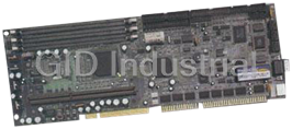
IEI ROCKY-P218A
Description
Full-size Single Board Computer. Intel Pentium II Support | Audio
Part Number
ROCKY-P218A
Price
Request Quote
Manufacturer
IEI
Lead Time
Request Quote
Category
Single Board Computers
Specifications
System Chipset
Intel 440BX
Form Factor
PICMG 1.0
E2Key: 1kbit user programmable EEPROM to store system ID, password etc
Real Time Clock: Industrial Lithium Battery providing 10-year data retention from -40ºC to 85ºC, 850mAh
Audio
Creative Sound Blaster 16 compatible, Roland MPU401 UART Mode compatible
BIOS
AMI Flash BIOS, Bootable from LS-120, ZIP or CD-ROM
Board Type
Full Size
Bus Interface
PCI and ISA bus (PICMG standard) ISAPLUS enhanced drive capability
Cache
512kB (on-board processor)
Chipset
Intel 440LX
Connector
Keyboard/Mouse: 6-pin Mini-DIN connector for Keyboard & Mouse (external splitter cable provided) 5-pin shrouded external keyboard connector Miscellaneous: Reset switch and key-lock switch Hard disk LED External speaker Sound Blaster Audio In / Out
CPU
Intel Pentium II 233 - 333MHz, Celeron 266 - 333MHz
Dimensions
338mm (L) x 122mm (H)
H/W Status Monitoring
LM78 to monitor Power Supply Status, CPU Fan Speed
I/O
Multi I/O Chipset: W83977, BIOS selectable setup Supports up to 4 Master PCI peripheral cards Two Ultra-DMA/33 IDE channels Supports up to 4 Ultra-ATA Hard Disk Drives Two RS-232 serial ports with 16C550 UART Parallel port (EPP/ECP) Floppy Disk Controller
Memory
3 x 168-pin DIMM sockets, up to 384MB SDRAM
Operating Humidity
0% to 95%, Non-condensing
Operating Temperature
Operating: 0ºC to 55ºC Storage: -20ºC to 85ºC
Power Consumption
With Pentium II 300MHz and 32MB SDRAM: +5V @ 7.5A, +12V @ 240mA, -12V @ 40mA
Power Supply
Power Management: ACPI Power Management / PC97 compliant
Processor
Intel Pentium II
SSD
DiskOnChip Socket (up to 288MB)
Watchdog Timer
6-stage watchdog timer (1s/2s/10s/20s/110s/220s) Can generate Reset or NMI
Datasheet

Extracted Text
–
All Rights Reserved.
Manual third edition Mar.15,1998
The information in this document is subject to change without prior notice in
order to improve reliability, design and function and does not represent a
facturer.
In no event will the manufacturer be liable for direct, indirect, special,
incidental, or consequential damages arising out of the use or inability to use
the product or documentation, even if advised of the possibility of such
This document contains proprietary information protected by copyright. All
rights are reserved. No part of this manual may be reproduced by any
mechanical, electronic, or other means in any form without prior written
permission of the manufacturer.
ROCKY-P218A is registered trademarks of Acquire Inc.,IBM PC is a
registered trademark of International Business Machines Corporation. Intel is
a registered trademark of Intel Corporation. AMI is registered trademarks of
Megatrends, Inc. Other product names mentioned herein are used
for identification purposes only and may be trademarks and/or registered
trademarks of their respective companies.
American
Trademarks
damages.
commitment on the part of the manu
@Copyright 1998
SBC
Pentium® II & Sound
P218A ROCKY
Contents
3
1.1Specifications..............................................................................4
1.2What You Have...........................................................................5
6
2.1..............................................................6
2.2...................................................................................8
2.3............................................. 9
2.4............................................................. 9
2.5................................................................9
2.6Watch-Dog Timer......................................................................
2.7DiskOnChip™ Flash Disk............................................................
2.8....................................................................
2.9...........................................................
3.1......................................................
3.2................................................
3.3Parallel Port...............................................................................
3.4Serial Ports................................................................................
1
14
14
13PCI E-IDE Disk Drive Connector
12Floppy Disk Drive Connector
12.........................................................3. Connection
11Creative Sound Function
11Clear CMOS Setup
10
10
System Memory DRAM
BIOS Flash Type Setting
Setting the CPU of ROCKY-P218A
Unpacking
ROCKY-P218A's Layout
............................................................2. Installation
..........................................................1. Introduction
3.5.......................................................
3.6ernal Switches and Indicators...............................................
3.7.......................................................................
3.8IrDA Infrared Interface Port .......................................................
3.9..........................................................................
3.10 Sound Function Connectors ......................................................
4.1Getting Start..............................................................................
4.2..............................................................
4.3.............................................................
4.4............................................................
4.5.......................................................................
4.6.........................................................
4.7....................................................
4.8 Hardware Monitor Setup ……………………………………………
2
Appendix A. Watch-Dog Timer
2
29..............................
27..................................................Key Function5. E
26
25PCI / PLUG AND PLAY Setup
24Power Management Setup
23Peripheral Setup
22anced Chipset SetupAdv
21Advanced CMOS Setup
20Standard CMOS Setup
19
19.................................................4. AMI BIOS Setup
17
17Fan Connector
17
16External Speaker
16Ext
15Keyboard/Mouse Connector
1
Introduction
Welcome to the ROCKY-P218A Pentium® II & Creative Sound
ISA/PCI form factor board, which comes equipped with high
performance multi-mode I/O, designed for the system
VARs that want to provide all the
performance, reliability, and quality at a reasonable price.
This board built-in ™
software utility. The DOC currently is available from 2MB to
™
An advanced high performance super AT I/O chip – Winbond
IDE interface are compatible with IBM PC/AT and XT
In addition, the ROCKY-218A provides Creative Sound
capability.
ViBRA 16X which provides full-featured,16-bit
compatibility,wave-table
WaveSynth™ Creative 3D Stereo
Technology™ and full-duplex capabilities.
which is 100% ISA/PCI compatible
3
standard.
chipset.with PCI 2.1
ROCKY-P218A uses the advanced INTEL Chipset,440LX
Enhancement
synthesis with Creative
audio with 100% Sound Blaster 16
The sound chip is
architecture's.
UARTs are compatible with the NS16C550. The parallel port and
W83977TF is used in the ROCKY-P218A board. Both on-chip
same DOC socket as an alternative solution.
can be used in the72MB. There also have PROMDISK-Chip
disk. User can use any DOS command without any extra
application. The DOC Flash Disk is 100% compatible to hard
(DOC) Flash Disk for embeddedDiskOnChip
manufacturers, integrators, or
performance Pentium® II Processor and advanced high
Single Board Computer. The ROCKY-P218A board is an
1.1 ons :
· : Pentium® II 233 - 333Mhz Processor
· : ISA bus and PCI 32-bit local bus,PCI 2.1 standard
·DMA channels : 7
·Interrupt levels : 15
· : Intel 440LX
·Real-time clock/calendar : in 440LX chipset, backup by industrial
Li-battery,3V/850mAH.
·RAM memory
EDO RAM module. The max. memory is up to 384MB.
·
·Ultra DMA/33 IDE Interface : up to four PCI Enhance IDE hard
drives. The Ultra DMA/33 IDE can handle data transfer up to
33MB/s. The best of all is that is new technology is compatible with
change for customer’s current accessory.
·Floppy disk drive interface : two 2.88 MB, 1.44MB, 1.2MB, 720KB,
or 360KB floppy disk drives.
· : NS16C550 compatible
·Bi-directional Parallel Port
·Built-in LM78 to monitor power supply voltage and fan speed
status.
·IrDA port : Support Serial Infrared(SIR) and Amplitude Shift
·USB port : Support two USB ports for future expansion.
·Watch-dog timer : can be set by 1,2,10,20,110 or 220 seconds
trigger the timer. Your program use hex 043 and 443 to control the
4
watch-dog and generate a system reset.
period. Reset or NMI was generated when CPU did not periodically
Keyed IR(ASKIR) interface.
UARTsTwo high speed Series ports
existing ATA-2 IDE specifications. So there is no need to do any
: 512KB Pipelined Burst SRAM in CPU.Second Cache memory
: Three 168-pin DIMM sockets support SDRAM and
Chipset
Bus
CPU
Specificati
·Flash Disk - ™:or PROMDISK-Chip™ : The Flash Disk
provide 100% compatible with hard disk. The built-in
Transparent Flash Block Management and Space Reclamation will
let customer to use the Flash Disk with DOS command, no need any
extra software utility.
·
·Mouse : PS/2 Mouse Port on-board.
· : +5V @ 7.5A
( Pentium® II 300MHz,32MB EDO RAM)
+12V @ 240mA ,-12V @40mA
·Operating Temperature : 0 ° ~ 55 °
1.2
In addition to this
includes the following items:
· ROCKY-218A Pentium
·
·
·
If any of these items is missing or damaged, contact the dealer
from whom you pur
product in the future.
5
materials and carton in case you want to ship or store the
chased the product. Save the shipping
Cable
6-pin Mini-Din to 5-pin Din Keyboard and Mouse Adapter
FDD/HDD Cable
Printer/RS-232 Cable
Single Board Computer® II & Sound
, the ROCKY-P218A packageUser's Manual
What You Have
C ( CPU needs Cooler)
Power Consumption
Keyboard connector
TrueFFS
DiskOnChip
2
Installation
information that you should be careful is described. The
2.1–
< reference next page >
6
P218A's LayoutROCKY
and watch dog timer, are also included.
configuration, such as CPU type selection, system clock setting,
jumpers and switches setting for the ROCKY-P218A's
the layout of ROCKY-P218A is shown, and the unpacking
This chapter describes how to install the ROCKY-P218A. At first,
2.2Unpacking
7
electricity.
while unpacking, as well as during installation. It is very
important that the instructions be followed correctly, to avoid
Do this only with the board place on a firm flat surface.
Note : DO NOT APPLY POWER TO THE BOARD IF IT HAS
8
Computer.
You are now ready to install your ROCKY-P218A Single Board
BEEN DAMAGED.
socketed IC's to make sure that they are properly seated.
Again inspect the board for damage. Press down on all the
up.
place it only on a grounded anti-static surface component side
After opening the cardboard carton, exact the system board and
shipping and handing damages on the board before processing.
handling may cause damage to your board. Be sure there are no
Inspect the cardboard carton for obvious damage. Shipping and
grounded at the same point as the anti-static mat.
The operator should be wearing an anti-static wristband,
The system board should be done on a grounded anti-static mat.
static damage, and to successfully install the board.
In this section, we describe the precautions you should take
electronic components that can be easily damaged by static
Your ROCKY-P218A Single Board Computer contains sensitive
2.3 Setting the CPU of ROCKY-P218A
· CPU Clock Setting :
CPU Speed/Clock JP3
1-3
60MHz
66MHz 2-4
CPU to Bus Multiple :
·
Multiplier 1-2 3-4 5-6 7-8
2.0 x CLOSE CLOSE CLOSE CLOSE
2.5 x CLOSE CLOSE OPEN CLOSE
3.0 x CLOSE OPEN CLOSE CLOSE
3.5 x CLOSE OPEN OPEN CLOSE
4.0 x OPEN CLOSE CLOSE CLOSE
4.5 x OPEN CLOSE OPEN CLOSE
5.0 x OPEN OPEN CLOSE CLOSE
CPU Frequency = CPU Clock x Multiplier for example
2.4 BIOS Flash Type Setting
· JP10 : Flash Type Setting
DESCRIPTION
2-35V Flash
1-2
The total capacity is from 8MB to 384MB.
9
only one DIMM module and can be populated in any order.
Customer can use
RAM ,8MB,16MB,32MB,64MB,128MB memory modules.
EDO
There are three 168-pin DIMM sockets to accept SDRAM or
2.5 System Memory DRAM
12V Flash
JP10
designed to handle the setting.
ROM,one is 12V programming and the other is 5V. JP10 is
There are two kind of Flash Chips can be used as BIOS
Pentium® II 266MHz = 66MHz CPU Clock x 4.0
JP1 :
JP3 :
2.6 Watch-Dog Timer
signal to start again, or activate NMI to CPU. The Watch-Dog
JP9 : Watch-Dog Active Type Setting
·
JP9DESCRIPTION
2-3RESET WHEN WDT TIME-OUT
1-2ACTIVATE NMI TO CPU WHEN WDT TIME-
OUT
DISABLE WDT
OPEN
· JP11 : WDT Time-Out Period
PERIOD 1-2 3-4 5-6 7-8
1 sec. OPEN OPEN CLOSE OPEN
OPEN OPEN CLOSE CLOSE
2 sec.
10 sec. OPEN CLOSE OPEN OPEN
20 sec. OPEN CLOSE OPEN CLOSE
CLOSE OPEN OPEN OPEN
CLOSE OPEN OPEN CLOSE
2.7 ™ Flash Disk
The ™
And ‘t need any extra software utility. It is just
“”,easy and reliable. Right now the DOC is available
from 2MB to 72MB.There also have PROMDISK-Chip™
memory address.
·
JP12
1-2
3-4
10
D000H
C800H
Address
DiskOnChip Memory Address Setting JP12 :
DiskOnChip will only share 8KB used with the same socket. The
can be
playplug and
DOS.Customer don
M-Systems. Because the DOC is 100% compatible to hard disk
Flash Disk Chip(DOC) is produced byDiskOnChip
DiskOnChip
220 sec.
110 sec.
Timer is disable by reading port 043H.
assume the program operation is abnormal and will issue a reset
be triggered before the time-out period ends, otherwise it will
The Watch-Dog Timer is enabled by reading port 443H. It should
5-6
If want to clear the CMOS Setup(for example forgot the
again.),you should close the JP4 pin 2-3 about 3
open again. Set back to normal operation
· JP4 : Clear CMOS Setup (Reserve Function)
JP4 DESCRIPTION
1-2 Normal Operation
2-3 Clear CMOS Setup
The on board Creative Sound provide a 100% Sound Blaster 16
compatible function. You can use the JP5 to enable or disable
the sound function.
JP5 : Enable/Disable on board Sound function ·
JP5 DESCRIPTION
CLOSE Enable Sound Function
OPEN
–
16-bit I/O –
SB I/O :
Default setting :
Adlib :
Default setting :
Default Setting :
IRQ : IRQ5,or IRQ7,or IRQ9,or IRQ10
Default Setting :
Default Setting : Channel 1 and 3
–
16-bit I/O Decoding, PnP ID –
Gameport :
11
200 to 20Fh(any address of I/O space)
CTL7005
Gameport ResourcesDevice 1
Channel 0,or Channel 1,or Channel 3DMA :
IRQ5
330-331h
300-301h,or 310-311h,or 320-321h,or 330-331hMPU-401 :
388-38Bh
388-38Bh,or 38C-38Fh,or 390-393h,or 394-397h
220-22Fh
220-22Fh,or 240-24Fh,or 260-26Fh,or 280-28Fh
CTL0043Decodin, PnP ID
Sound Blaster ResourcesDevice 0
The Creative Chip will share some I/O resource as follows,
Disable Sound Function
2.9 Creative Sound Function
mode,close pin 1-2.
seconds,then
password you should clear the setup and then set the password
2.8 Clear CMOS Setup
D800H
Default
3
Connection
3.1Floppy Disk Drive Connector
CN3 : FDC CONNECTOR
·
1GROUND2REDUCE WRITE
3GROUND4N/C
5GROUND6N/C
7GROUND8
9GROUNDMOTOR ENABLE A#
GROUNDDRIVE SELECT B#
GROUNDDRIVE SELECT A#
GROUNDMOTOR ENABLE B#
GROUNDDIRECTION#
GROUNDSTEP#
GROUNDWRITE DATA#
GROUNDWRITE GATE#
GROUNDTRACK 0#
GROUNDWRITE PROTECT#
GROUNDREAD DATA#
GROUND
GROUNDDISK CHANGE#
12
3433
SIDE 1 SELECT#3231
3029
2827
2625
2423
2221
2019
1817
1615
1413
1211
10
INDEX#
DESCRIPTIONPIN NO.DESCRIPTIONPIN NO.
connector cable.
ROCKY-P218A board equipped with a 34-pin daisy-chain driver
indicators to the ROCKY- P218A board.
This chapter describes how to connect peripherals, switches and
201h
3.2
You can attach four IDE( Integrated Device Electronics) hard
disk drives to the ROCKY-P218A IDE controller.
CN2 (IDE 2) : Secondary IDE Connector
·
PIN NO.DESCRIPTIONPIN NO.DESCRIPTION
1RESET#2GROUND
3DATA 74DATA 8
5DATA 66DATA 9
7DATA 58DATA 10
9DATA 4DATA 11
DATA 3DATA 12
DATA 2DATA 13
DATA 1DATA 14
DATA 0DATA 15
GROUNDN/C
N/CGROUND
IOW#GROUND
GROUND
N/C
N/CGROUND - DEFAULT
INTERRUPT
N/C
HDD ACTIVE#GROUND
13
4039
HDC CS1#38HDC CS0#37
SA236SA035
34SA133
IOCS16#-DEFAULT3231
3029
BALE - DEFAULT2827
26IOR#25
2423
2221
2019
1817
1615
1413
1211
10
CN1/CN2 : IDE Interface Connector
CN1 (IDE 1) : Primary IDE Connector
PCI E-IDE Disk Drive Connector
3.3 Parallel Port
· CN4 : Parallel Port Connector
PIN NO.DESCRIPTIONPIN NO.DESCRIPTION
1STROBE#2DATA 0
3DATA 14DATA 2
5DATA 36DATA 4
7DATA 58DATA 6
9DATA 7ACKNOWLEDGE
PRINTER SELECTAUTO FORM FEED #
ERROR#
PRINTER SELECT LN#GROUND
GROUNDGROUND
GROUNDGROUND
GROUNDGROUND
GROUND
3.4Serial Ports
·
PIN NO.DESCRIPTION
1DATA CARRIER DETECT (DCD)
2
3
4DATA TERMINAL READY (DTR)
5
6
7REQUEST TO SEND (RTS)
8
9
·
14
CN5 : Serial Port 10-pin Header( ACE1)
RING INDICATOR (RI)
CLEAR TO SEND (CTS)
DATA SET READY (DSR)
GROUND (GND)
TRANSMIT DATA (TXD)
RECEIVE DATA (RXD)
CN8 : Serial Port DB-9 Connector( ACE0 )
UARTs with Read/Receive 16 byte FIFO serial ports.
The ROCKY-P218A offers two high speed NS16C550 compatible
25
2423
2221
2019
1817
INITIALIZE1615
1413
PAPER EMPTY12BUSY11
10
CN4.
an on-board parallel port, accessed through a 26-pin flat-cable connector
This port is usually connected to a printer, The ROCKY-P218A includes
3.5Keyboard/Mouse Connector
· CN7 : 5-pin PS2 Mouse Connector
PIN NO.DESCRIPTION
1MOUSE DATA
2N/C
3GROUND
4
5MOUSE CLOCK
·
PIN NO.DESCRIPTION
1
2KEYBOARD DATA
3N/C
4GROUND
5
· CN10 : 6-pin Mini-DIN Keyboard/Mouse Connector
PIN NO.DESCRIPTION
1KEYBOARD DATA
2MOUSE DATA
3GROUND
4
5
6MOUSE CLOCK
which is connected to the CN10 and provide a PS2 mouse and
5-pin DIN keyboard connector.
15
Please note the board includes a keyboard/mouse adapt cable
KEYBOARD CLOCK
+5V
+5V
KEYBOARD CLOCK
CN9 : 5-pin Header Keyboard Connector
+5V
The ROCKY-P218A provides two keyboard/mouse connectors.
NC 10 GND 9
RI 8 DTR 7
CTX 6 TXD 5
RTS 4 RXD 3
DSR 2 DCD 1
Description Pin No. DescriptionPin No.
3.6 External Switches and Indicators
monitoring and controlling your CPU board. All the functions are
J1 : Pin 1-3 External Speaker
Pin 5-6 Reset Switch
Pin 7-8 IDE LED
Pin 11-13 Power LED
Pin 14-15
Pin 9,10,16-20 Reserved
1 11. +5V
2. 12. N/C
3. +5V 13.
4. 14.
5. 15.
6. 16.
7. +5V 17
8.Active# 18.
9. 19.
10. 20.
3.7 USB Port Connector
Pin 1-4 for USB 0
Pin 5-8 for USB 1
1. 5.
2. DATA- 6. DATA-
3. DATA+ 7. DATA+
4. 8.
16
GROUND GROUND
VccVcc
J2 : 2 ports USB Connector
I/O bus expansion.
The ROCKY- P218A built-in two USB ports for the future new
HDD
Ground
Ground External Reset
KeyLock Signal
Ground
NC
Speaker Signal
J1 Pin Assignment :
KeyLock
in the J1 connector.
There are several external switches and indicators for
3.8
The ROCKY-P218A built-in a
Infrared(SIR) or Amplitude Shift Keyed IR(ASKIR) interface.
IrDA port have to set SIR or ASKIR model in the
BIOS’’
·
PIN NO.DESCRIPTION
1VCC
2
3
4
5
6
3.9 Fan Connector
to the cooling fan. In the connector there have a “” pin .
The rotation pin is to get the fan’
only specified fan offers the rotation signal.
·
PIN NO.DESCRIPTION
1
2
3
3.10 Sound Function Connectors
’s Creative Sound Function provides
several connector for audio in and audio out. The details are :
J3 : MIDI/GAME Port ·
17
The ROCKY-P218A
Ground
12V
Rotation Signal
J10/J11 : CPU Fan Connector
the system BIOS could recognize the fan speed. Please note
s rotation signal to system. So
rotation
chassis fan connector. These connectors can supply 12V/500mA
The ROCKY-P218A provides CPU cooling fan connector,
CIRRX
IR-TX
Ground
IR-RX
FIR-RX
IrDA connector CN6 :
COM 2 will be disabled.
s COM 2. Then the normal RS-232s Peripheral Setup
When use the
IrDA port which support Serial
IrDA Infrared Interface Port
JRC0 JRC2
GROUND MIDI OUT
GROUND JRC3
JRC1
NC
· J5 : MICROPHONE IN
J6 : LINE IN
·
J7 : CD AUDIO IN(MITSUMI)
·
PIN NO.DESCRIPTION
1 JCD-L
2GROUND
3GROUND
4JCD-R
·
PIN NO.DESCRIPTION
1GROUND
2JCD-L
3GROUND
4JCD-R
· J9 : LINE OUT(Speak Out)
18
J8 : CD AUDIO IN(SONY)
16 5V 8.
MIDI IN 15 JOYF1 7.
JOYF3 14 6
13 5
12 4
11 3
JOYF2 10 JOYF0 2
5V 9 5V 1
DescriptionPin No. DescriptionPin No.
4
provide maximum flexibility in configuring the system by offering
4.1 Getting Start
test ,initialization and system configuration verification. After the
" Hit DEL if you want to run SETUP"
The following screen will be displayed at this time.
Auto Configuration with Fail Safe Settings will
load the minimized settings for Troubleshooting. The
Auto Configuration with Optimal Settings will
will modify all applicable settings.
19
load optimized defaults for regular use. Choosing this setting,
When choose
performance should be very poor when use this setting.
When choose
To access AMI PCI/ISA BIOS Setup program, press key.
POST routines are completed, the following message appears :
Self-Test routines. These routines will be executed for system
When power on the system, the BIOS will enter the Power-On-
usage of these features.
requirements. This chapter is written to assist you in the proper
various options which may be selected for end-user
configuration. The AMI BIOS setup program is designed to
The ROCKY-P218A uses the AMI PCI/ISA BIOS for system
AMI BIOS Setup
4.2 Standard CMOS Setup
configuration. The main function is for Date/Time setting and
Floppy/Hard Disk Drive setting. Please refer the following screen
For IDE hard disk drive
Use the IDE HDD AUTO DETECTION in the main menu to
automatically enter the drive specifications.
Manually enter the specifications by yourself from
”“ option.
20
Userthe
3.
2.
bootup.Use the Auto setting for detection during 1.
setup procedure,
possible
setup,please check the following
for this setup.
The Standard CMOS Setup is used for basic hardware system
‘
best performance of the ROCKY-P218A board. As for normal
‘t have to change any default setting.
The default setting is pre-set for most reliable operation.
“”“Primary Display” to
““ for the application which don’
21
display.
t need keyboard and Absent
and System KeyboardCustomer can set
operation customers don
s tuningThis Advanced CMOS Setup is designed for customer
4.3 Advanced CMOS Setup
4.4 Advanced Chipset Setup
ChipSet(Intel
‘s
Fixed Memory Hole : Enable or Disable
Memory from 15MB and up will be unavailable to the system
22
because expansion cards can only access memory up to 16MB.
ISA expansion cards that specifically require this setting.
This setting reserve 15MB to 16MB memory address space for
un-stable.the system could be running
registers. Please carefully change any default setting ,otherwise
ChipSet440LX). These options are used to change the
This setup functions are almost working for
4.5 Peripheral Setup
This setup is almost working for Multi-I/O Chip(W83977F ).
‘
Please carefully change any default setting to meet your
Serial Port 2. If you are using the IrDA port,you have to set this
23
port accordingly.
application need perfectly. The only special concern is Onboard
s registers.ChipSetThese options are used to change the
4.6 Power Management Setup
‘“”
the video display and hard disk to save energy for example. The
Power Management/APM : Disable, Max Saving, Min Saving,
or User Defined
Max Saving puts the system into power saving mode after a
brief inactivity period. Min Saving is almost the same as Max
Saving except that the inactivity period is longer. User Defined
requirement.
) have to be
DEVICE=C:\DOS\POWER.EXE in your CONFIG.SYS
24
Under DOS environment, you need to add
enters suspend mode activated by the Power Management.
installed to keep the system time updated when the computer
Note : Advanced Power Management(APM
allows you to set power saving options according to your
power management setup screen is as following,
function. The features could shut downgreens P218A board
Power Management Setup help user handles the ROCKY-
Under Windows 3.x and Windows 95,you have to install
“”
Will appear in the “”
‘“”
INTA#,thus all
installed PCI slots must be set to this value..
Plug and Play Aware O/S : Yes or No
When
25
to prevent reassigning of interrupt settings, select setting to No.
OS when the setting is Yes. When a non-PNP OS is installed or
PNP OS is installed, interrupts may be reassigned by the
function. All PCI bus slots on the system use
PCIs The setup help user handles the ROCKY-P218A board
4.7 PCI / PLUG AND PLAY SETUP
Control Panel
Powerlabeled
Windows with APM feature. A battery and power cord icon
4.8 Hardware Monitor Setup
‘
implemented by on board LM78 chip. The voltage monitoring
will cover +5V,+12V,-12V,and –5V. And there have two fan
5
26
connectors for system and CPU fan.
board system voltage and fan speed. The function is
s onThe setup help user monitor the ROCKY-P218A board
2
E Key™ Function
2
™ function
2
™ you could free to
store the ID Code, Pass Word, or Critical Data in the 1Kbit
EEPROM. Because the EEPROM is nonvolatile memory, you
’t have to worry the losing of the very important data.
2
Basically the E™
2
™ you should have the utility in
the package. The software utility will include four files as follows,
E2KEY.OBJ
EKEYDEMO.C
EKEYDEMO.EXE.
The E2KEY.OBJ provides two library function for user to
2
integrate their application with E™ function. These library
are written and compiled in C
format. Please check the following statement, then you will know
how to implement it easily.
unsigned
2
/* This function will return the E™’
void write_e2key(unsigned int address,unsigned data)
2
/* This function will write the given data to E™
The address range is from 0 to 63. The data value is from 0 to
0xffff. */
27
at address.KEY
address range is from 0 to 63. Return data is one word,16 bits */
s data at address. TheKEY
int address)int read_e2key(unsigned
(read_e2key and write_e2key)
KEY
README.DOC
KEYWhen you start to use the E
write) each word at any time.
configured to 64 words(from 0 to 63). You could access(read or
is based on a 1Kbit EEPROM which isKEY
don
KEYfor system integrator. Based on the E
KEYThe ROCKY-P218A provides an outstanding E
EKEYDEMO.C code at first.
2
™
’
Appendix A. Watch-Dog Timer
The Watch-Dog Timer is provided to ensure that standalone
28
external EMI or a software bug. When the CPU stops working
caused the CPU to crash. This condition may have occurred by
systems can always recover from catastrophic conditions that
port, otherwise will be not working.
s parallelparallel port. So you should enable the ROCKY-618V
function is based on the working ofKEYPlease note the E
To easy start to use the function, please refer the include
maskable interrupt (NMI) to bring the
The Watch-Dog Timer is controlled by two I/O ports.
Enable the refresh the Watch-Dog
(hex)Timer.
Disable the Watch-Dog Timer.
(hex)
To enable the Watch-Dog Timer, a read from I/O port 443H
must be performed. This will enable and activate the countdown
timer which will eventually time out and either reset the CPU or
this reset condition does not occur, the Watch-Dog Timer must
A tolerance of at least 30% must be maintained to avoid
disk I/O that can be very time consuming. Therefore if the time
29
Dog Timer, otherwise the system will reset.
Note: when exiting a program it is necessary to disable the Watch-
be read within 7 seconds.
out period has been set to 10 seconds, the I/O port 443H must
unknown routines within the operating system (DOS), such as
jumper group JP11.
This must be done within the time out period that is selected by
be periodically refreshed by reading the same I/O port 433H.
cause an NMI depending on the setting of JP9. To ensure that
Read043
Read443
system back to a known state.
reset (cold boot) or a non-
correctly, hardware on the board will either perform a hardware
Frequently asked questions
Why do business with IEI Boards?

Will there be a warranty for the ROCKY-P218A?
Which companies are available as carriers?
I don't live in the USA. Will IEI Boards work with me?
Will IEI Boards accept my preferred method of payment?
Why buy from GID?

Quality
We are industry veterans who take pride in our work

Protection
Avoid the dangers of risky trading in the gray market

Access
Our network of suppliers is ready and at your disposal

Savings
Maintain legacy systems to prevent costly downtime

Speed
Time is of the essence, and we are respectful of yours
Related Products

LV Pentium M 1.4 GHz with 1 MB L2 cache

IEI EB-2810/ACE-816A Embedded chassis with ACE-816A 150W ATX power supply

IEI EB-2850GB-8450/ACE-4518AP CPU Board - Embedded chassis for NOVA-8450, with ACE-4518AP-RS,black, ...

IEI ECW-181BS2WD CPU Board - Embedded system with WAFER-GX, AMD Geode GX-466 333MHz CPU, fanless, DC...
Embedded system with WAFER-LUKE, VIA LUKE 1GHz CPU,fanless, DC 12V in, sliver grey, RoHS
IEI ECW-181BS3WD CPU Board - Embedded system with WAFER-LUKE, VIA LUKE 1GHz CPU,fanless, DC 9~36V in...
Request a Quote

The quote request has been received
Close

Facing challenges or have inquiries? Feel free to contact us!
Call Us +1-469-283-2440
What they say about us
FANTASTIC RESOURCE
One of our top priorities is maintaining our business with precision, and we are constantly looking for affiliates that can help us achieve our goal. With the aid of GID Industrial, our obsolete product management has never been more efficient. They have been a great resource to our company, and have quickly become a go-to supplier on our list!
Bucher Emhart Glass
EXCELLENT SERVICE
With our strict fundamentals and high expectations, we were surprised when we came across GID Industrial and their competitive pricing. When we approached them with our issue, they were incredibly confident in being able to provide us with a seamless solution at the best price for us. GID Industrial quickly understood our needs and provided us with excellent service, as well as fully tested product to ensure what we received would be the right fit for our company.
Fuji
HARD TO FIND A BETTER PROVIDER
Our company provides services to aid in the manufacture of technological products, such as semiconductors and flat panel displays, and often searching for distributors of obsolete product we require can waste time and money. Finding GID Industrial proved to be a great asset to our company, with cost effective solutions and superior knowledge on all of their materials, it’d be hard to find a better provider of obsolete or hard to find products.
Applied Materials
CONSISTENTLY DELIVERS QUALITY SOLUTIONS
Over the years, the equipment used in our company becomes discontinued, but they’re still of great use to us and our customers. Once these products are no longer available through the manufacturer, finding a reliable, quick supplier is a necessity, and luckily for us, GID Industrial has provided the most trustworthy, quality solutions to our obsolete component needs.
Nidec Vamco
TERRIFIC RESOURCE
This company has been a terrific help to us (I work for Trican Well Service) in sourcing the Micron Ram Memory we needed for our Siemens computers. Great service! And great pricing! I know when the product is shipping and when it will arrive, all the way through the ordering process.
Trican Well Service
GO TO SOURCE
When I can't find an obsolete part, I first call GID and they'll come up with my parts every time. Great customer service and follow up as well. Scott emails me from time to time to touch base and see if we're having trouble finding something.....which is often with our 25 yr old equipment.
ConAgra Foods